In the previous guide, we looked at the basic settings for setting up the LaserWeb workspace and pushing out your first GCODE. In this guide, we will look at the advanced settings that will allow you to speed up your workflow but also make tasks such as aligning mirrors a lot easier.
The Comms Tab:
The first thing we need to briefly touch on, however, is the “Comms” tab of the LaserWeb control panel. In the last tutorial, we skipped it as it was assumed that you would be uploading the GCODE directly to an SD card to be executed on the laser cutter. However, now is the time to take a look the scenario where you would generate and execute the GCODE file from LaserWeb itself. To me, this was the reason why I chose LaserWeb over other laser cutting GCODE generators (like EstlCam or even Fusion360 CAM), as the convenience of running a GCODE from the “slicer” (pardon the use of 3D printer lingo here) is really unparalleled.
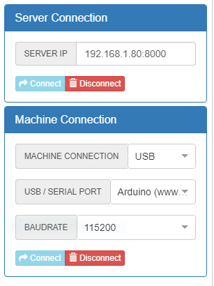
The Comms tab comprises two sections – one for the “Server Connection” and one for the “Machine Connection”. The former is only relevant if you are using the Raspberry Pi LaserWeb server (which I do) while the latter will be relevant for all machines that are plugged into the computer running the LaserWeb frontend (Frontend refers to the user-facing application, that is the software you have been using the whole time).
For the Server Connection, you will need to input the IP address of your Raspberry Pi running the LaserWeb server. This can be done by accessing the admin panel of your router.
For the Machine Connection, the most likely option you will be choosing is “USB” (because if I am not wrong the ESP8266 option is deprecated). If you have connected your board to your computer running LaserWeb via USB, you should see the device pop up on the USB/Serial Port list. As for the baudrate, you should choose the baudrate as defined by your controller firmware.
After choosing the settings, connect to the machine and server by clicking the “Connect” button. If it is successful the button should become greyed out (like in the picture) and you should see logs coming in from the terminal.
The Control Tab:
The control tab is where you jog your machine, home axes, and run jobs after generating GCODE. There are three main sections in the Control Tab: Coordinates readout, Job/Movement Controls, and Macros.
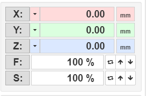
In the Coordinates Readout Section, the current position of the Laser Head is displayed. Also displayed are the feedrates for all axes as a percentage of the default feedrate (this can be changed in the controls section).
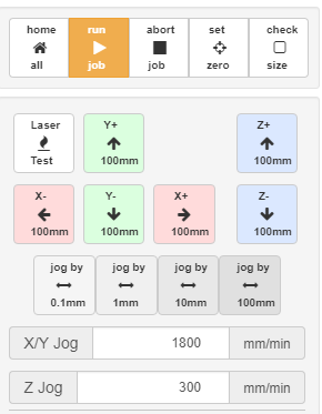
The Controls Section is by the the most useful. From here, you control the status of a job (first row) as well as homing, setting zero and checking size.
Home All: Runs the Homing GCODE command set in Settings.
Run Job: Executes the current GCODE job that has been generated.
Abort Job: Halts the transmission of GCODE commands to the control board but does not issue any “GCODE END” commands. Hence most of the time the laser will still be left on (at full power) where it was last positioned before the stop was called. As it is imperative to immediately disconnect and reconnect the machine (via the “connect” button in Comms tab).
Set Zero: This moves the zero (or home) position to whatever position the laser head is currently on (the blue dot represents the laser head).
Check Size: This sends commands to the machine to lightly etch the perimeter of the workspace in laser web. This allows you to check to see if any parts are outside the workable cutting area of your laser cutter.
This tab contains the various preset commands specified under Macros in settings.
Macros are essentially shortcuts that allow you to issue complex commands via a press of a button instead of manually typing them out. More on that later when we discuss the advanced settings of LaserWeb.
Advanced Settings:
Now we will take a detailed view of the advanced settings to see how we can further customize our setup and enable custom features.
The settings tab comprises many sections and as such, we will take a look at each section at a time.
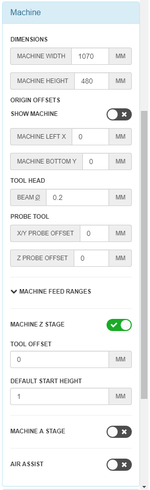
Machine:
Having discussed the Dimensions settings in the previous guide, we will discuss the other settings parameters for the Machine tab.
Show Machine – this radio button toggles an outline of the workable cut area of the laser cutter. This is useful as a visual indicator of whether or not your parts spill out of the cutting area of the laser cutter. However, for more fine-tuned adjustments to the position of your parts, it is still best to use the coordinate positioning dialog box as mentioned.
Tool Head (Beam) – This sets the diameter of the laser beam in accounting for kerf thickness. Generally I have found that leaving this value on the default value has worked fine.
Probe Tool: If your machine has a Z-probe (such as an inductive sensor, BL-Touch or a servo-driven endstop), here is where you specify the offsets:
X/Y Probe Offset – this is only relevant for CNC machines with an X/Y touch probe. For Laser Cutters this setting is irrelevant.
Z Probe Offset – you can specify the Z probe offset from the laser head nozzle tip. A negative number indicates that the Z probe is below the nozzle tip (most likely the case), vice versa. You may want to experiment with this value as well as the Tool Offset and Default Start Height setting to adjust your height from the workpiece.
Note: These settings are only relevant if your machine has a moving Z axis.
Machine Z Stage – toggles the Z-axis settings depending on whether you have a Z-axis on your machine.
Tool Offset: This determines how far above the Z home position your tool is. Honestly, I would leave this at 0 and adjust the Z Probe Offset parameter (or the Default Start Height) instead.
Default Start Height – sets the default start height for operations in the Files tab. Set this to the value determined from experimenting with various heights to find the focal length of the laser.
Machine A Stage – Toggles the A-Axis (rotational axis) of the machine (if the machine has one).
Air Assist – Toggles GCODE control for Air Assist. On most machines, Air Assist is hard wired to the power switch (when the machine turns on, air assist automatically turns on). However if your machine has GCODE controlled Air Assist, you can specify the GCODE to turn it on and off here.
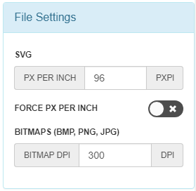
File Settings:
This tab controls the file settings for imported documents into LaserWeb. I recommend keeping the values here at their default.
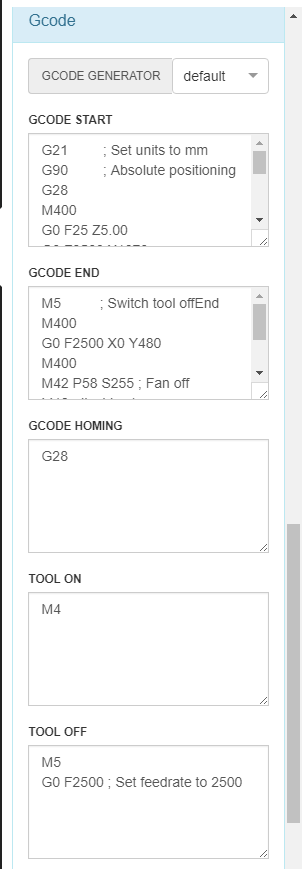
GCODE:
This is by far the settings page that will save you the most time.
We have discussed the GCODE Generator dropdown in the previous guide.
GCODE START – Sets the GCODE to be executed at the start of a job. Typically this involves homing axes. A typical example would look like this:
G21 ; Set units to mm
G90 ; Absolute positioning
G28 ; Home all axes
M400 ; Wait for previous moves to be completed
If your machine does not have a Z axis you can replace the G28 command with G28 X Y.
If your machine has no endstops whatsoever, you can manually specify the position of the laser head using G92 X(X-cood) Y(Y-cood) such as example G92 X1070 Y480. Note: You must manually move the laser head to specified position because the machine will think that it is at the position you specified, even if it is not.
Here is also a good time to turn on any internal lights, exhaust fans or air assist (if you did not specify air assist in Machine) through GCODE. For example:
G21 ; Set units to mm
G90 ; Absolute positioning
G92 X1070 Y480 Z2.0
M400 ; wait for previous GCODE to be executed
M42 P58 S0 ; Fan on
M106 ; lights on
G0 F2500 ; Set feedrate to 2500
M400 ; wait for previous GCODE to be executed
GCODE HOMING – this sets the GCODE to run when you press the Home All button on the Control tab.
TOOL ON – This sets the GCODE to turn on the tool. Typically this is either M3 or M4 for laser cutters.
TOOL OFF – This sets the GCODE to turn off the tool. For laser cutters this is typically M5. In my case you can see I have added an extra line: G0 F2500. This is because travel feedrates are not specified in GCODE for laser web as it is assumed the controller firmware overrides G0 moves without Feedrate specified. Hence if you want to set the feedrate, placing it after the M5 command is a nifty trick as the TOOL OFF GCODE is always executed before a travel move.
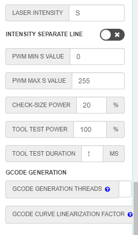
LASER INTENSITY – This sets the alphabet that sets laser intensity. For Marlin this is “S”.
INTENSITY SEPARATE LINE – As per the documentation, this has to be activated if you are running Marlin v2.0 or older. This formats the GCODE to put the intensity on a different line as the motion GCODE.
PWN MIN S VALUE – This sets the minimum PWM value (which should be 0).
PWM MAX X VALUE – This sets the maximum PWM value (which should be 255) assuming you are using an Arduino Mega with RAMPS1.4
CHECK-SIZE POWER – The laser power when checking the size of the cut area when you click on Check Size in the Control tab. This should be set to a low value to avoid cutting the material.
TOOL TEST POWER – The laser power when pulsing the tool to test the laser. Most commonly used during mirror alignment. This should be set at 100%.
TOOL TEST DURATION – The length of the pulse when pulsing the tool. This should be short at around 50ms max.
GCODE GENERATION THREADS – A larger number means more resources will be dedicated to generating GCODE which means a faster generation time, but also requires a more powerful processor.
GCODE CURVE LINEARIZATION FACTOR – A larger number leads to an increase in the precision of curves at the cost of GCODE generation time.
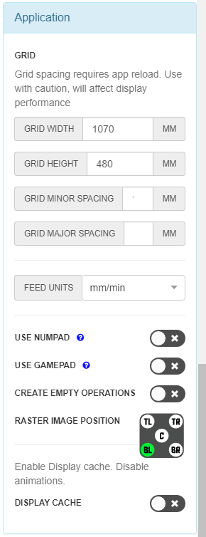
Application:
This controls the display and GCODE settings for the application.
GRID
Grid Width – Specifies the width of the grid. Typically this should be the width of your cutting area.
Grid Height – Similar to grid width.
Grid minor spacing – sets the spacing of the small subdivisions in the grid.
Grid major spacing – sets the spacing of the large subdivisions in the grid
Feed units – sets the units for feedrate (typically mm/min).
USE NUMPAD – toggles jogging control using Numpad
USE GAMEPAD – SImilar to USE NUMPAD but for a gamepad
RASTER IMAGE POSITION – Sets the position of a raster image when loaded into LaserWeb. Typically you would want to position this at the corner of your origin.
DISPLAY CACHE – Enable it to allow LaserWeb to run on old hardware with low processing power.
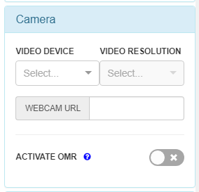
Camera:
LaserWeb allows you to view a camera stream from inside the application itself. To use this feature, we will need to either have a hardware camera (USB camera) connected to the computer running the frontend or a IP camera on the same network as the computer running the frontend.
Unfortunately, LaserWeb has yet to roll out support for a Raspberry Pi / webcam camera on the LaserWeb Pi server. However, it is possible to run an MJPEG / Motion stream on the raspberry pi and include the webcam URL here.
ACTIVATE OMR – Toggles an experimental Optical Mark Recognition feature to allow for stock alignment.
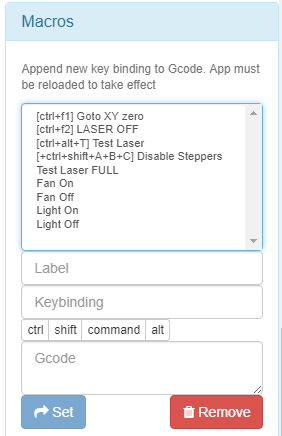
Macros:
By far the most useful feature in LaserWeb, Macros allow you to create shortcuts for commonly-used GCODE commands, making repetitive tasks like mirror alignment a lot easier.
To create a macro, simply key in a Label for the macro (typically something descriptive) as well as an optional Keybinding, followed by the GCODE. You can key in multiple lines of GCODE.
Then, click on the blue Set button to create the Macro. You should then see the Macro pop up in the list at the top. To remove a Macro, simply select the Macro from the list and click the red Remove button.
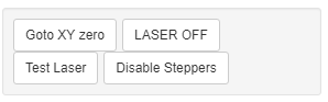
Here are some really useful Macros I use:
Disable Steppers: M18
Test Laser: M3 S125; G4 P50; M5
I had to create a Macro for this as the Laser Test button did not work for me.
Move to origin: G0 X1070 Y480 F3000
Fan ON/OFF: M42 P58 S0/255
and the list goes on!
You can also create Macros to move the laser head to the corners of the cut area, allowing for easy mirror alignment without having to constantly spam the move buttons on the Control tab.
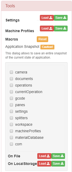
Tools:
The Tools tab is where you can find tools that will help you copy and migrate your LaserWeb settings and Machine Profiles to other computers, useful if you would like to prepare files and generate GCODE at home before heading down to your workshop to run the job.
As with the Workspace controls in the File tab, you can load settings with the read Load button and save settings with the green Save button. Do note that similar to the workspace tab, you must replace existing files with a new file if you want to save changes.
Saving your settings is also useful when troubleshooting your setup on forums. Typically the forum will request that you copy and paste the settings from the JSON source file saved so that others can refer to your settings and help you troubleshoot your problem.
Below are options to save entire application snapshots, with a series of checkboxes to determine which elements to save.
I would personally discourage this as there are many factors here that may be overlooked when trying to open the snapshot on another computer (for example Comms). As such it is best to only port over workspaces, settings, and machine profiles and configure the other settings from scratch when shifting to another computer.
And there we have it. A breakdown of all the settings in LaserWeb. In the next tutorial, we will be looking at the entire process of creating, ordering, and converting 2D designs into GCODE, as well as covering the practical tips and tricks you can use to save even more time while generating GCODE.