Having posted about my laser cutter, I thought it would be apt for me to do a short tutorial on LaserWeb, the software I use to generate the laser towpaths (the various sequence of steps the laser cutter is to take to cut out the part from a piece of sheet material) and convert that into GCODE (machine code – instructions for the laser cutter to move the motors and turn on/off the laser head).
Having used Estlcam back in the days when I was still relatively new to CNC machines and followed the MPCNC project to the Tee, LaserWeb looks pretty similar on the onset. However, there are a few quirks worth noting to help you speed up your workflow and reduce the time spent preparing files.
This guide is the first installment of a series dedicated to explaining LaserWeb. In this post, we will be discussing the basic functions of LaserWeb and how you can get started with generating your first GCODE and making your first cut.
Overview:
First and foremost, a brief overview of the Graphical User-Interface of the LaserWeb. As with other laser cutter controllers, LaserWeb features a central grid where toolpaths can be generated from files.
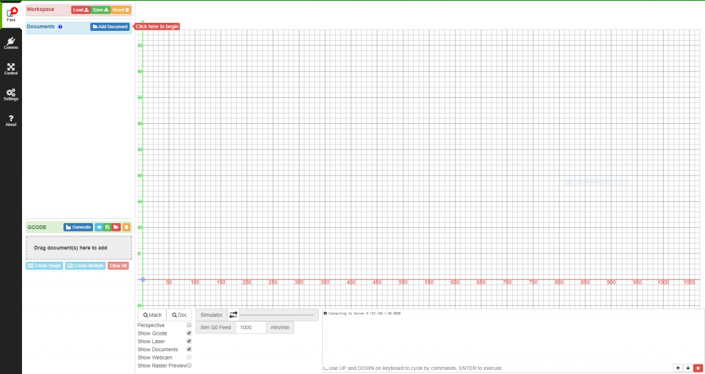
At the bottom of this page, you will find controls for the visibility of various elements such as GCODE, Laser Head and Webcam.
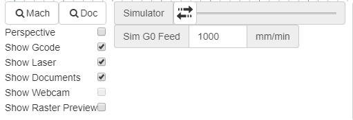
Often times I find it useful to turn the visibility of the document and the GCODE off and on respectively to check that the toolpaths have been generated correctly.
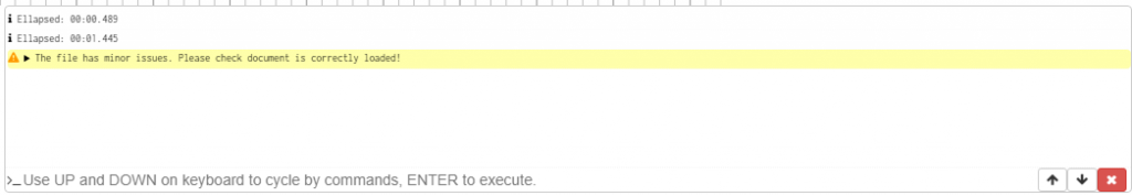
To the left of this, you will find a terminal window where messages can be sent and received from the controller board. This is also where you can send GCODE to the controller.
Before you Begin – Basic Setup:
Before you start importing files and generating toolpaths, it is of utmost importance that you create a machine profile with all the relevant dimensions of your workspace. The last thing you want is to have spent half an hour arranging items and generating toolpaths only for it to be too big for your machine cut area.
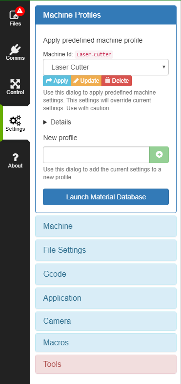
First, head over to the settings tab and click on the “Machine” submenu:
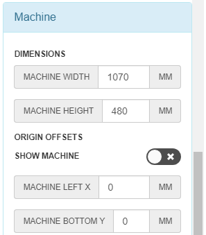
Then input the dimensions of your cut area under “Machine Width” and “Machine Height”. Also input any left or bottom offsets your machine might have (such as say due to the laser head not being able to reach all the way to the edges of the bed etc).
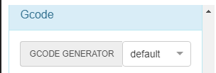
Also under the “Gcode” submenu, select “default” if you are using GRBL or Marlin that is version 2.0.6 or above. If you are using Marlin of version 2.0 and below, select “Marlin” instead. You can read more about this on the LaserWeb official wiki page.
Then head over to the top of the machine tab and add a new machine profile by typing in the name of the new profile (i.e “Laser Cutter”) and hitting the green plus icon. This should thus save all your machine settings under a machine profile, allowing you to quickly change between profiles without having to re-key in everything again.
As mentioned at the beginning, this is a very quick and dirty guide to help you generate GCODE as soon as possible. In future guides we will delve into the more advanced settings of LaserWeb.
Loading Files – The Files Tab
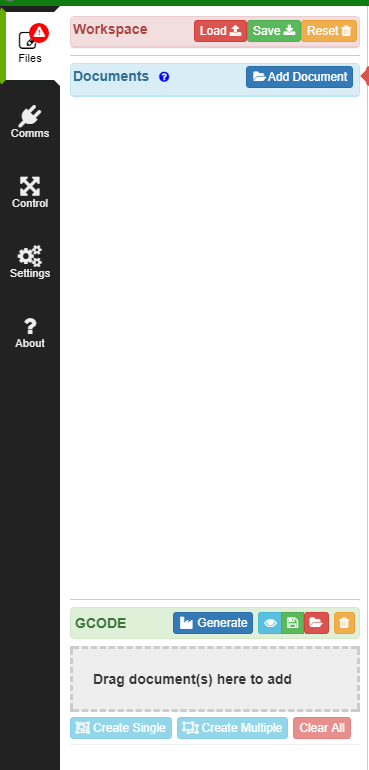
The Files tab is where you upload and manage designs to convert into toolpaths. Right at the top are workspace controls. A workspace can be thought of as a “snapshot” of the LaserWeb Frontend application containing not only files but also generated toolpaths and their respective settings. More on that later. You may want save a Workspace for future reference/use as toolpath generation can be rather time-consuming. To do so, click on the green “Save” button and the workspace will be saved as a generic file:
To reset the Workspace, click on the yellow “Reset” button. Note that all unsaved changes will be lost. Thankfully, LaserWeb prompts you for confirmation before doing this.
To load a Workspace when starting up LaserWeb, click on the “Load” button and select the file to which your workspace was saved:
It is worth noting that the “Save” button only saves workspaces at the point of pressing save and there is no autosave feature. Moreover, LaserWeb does not prompt you to save the workspace when closing the application and as such, it is very possible to lose all your work if you forget to hit save. As such, I frequently save the workspace after every major change (such as after generating a single toolpath) to avoid wasting my effort. Also, pressing the “Save” button will open a dialog box to save the workspace to a file, even if the workspace has been saved previously. Thus simply replace the old file with the new one and you’ll be on your way.
To load a Document (usually SVG, DXF or PNG although I would personally recommend SVG), click on the blue “Add Document” button and select the document from your local filesystem. This should present an outline of the paths in your design in the preview grid. **Note: LaserWeb will only work on paths and not objects (SVG).

The region below the “Documents” button will also be populated with your file, with subfolders appearing under parents etc. All pretty standard and intuitive. Selecting entities is thus very straightforward: clicking on a parent selects all its child entities and they will be highlighted in blue in both the Documents dropdown list as well as the preview window. You can also find particular entities by clicking on them in the preview grid and looking for them in the file dropdown panel. For example:
Before we start generating toolpaths, it is important to ensure that the design is positioned correctly on the grid. As mentioned earlier in Basic Settings, we need to ensure our design can physically fit into the available cut area of our machine. Laser Web’s origin is always at the bottom left corner of the grid where the markings are 0,0. As of now there is no way to change the position of origin.
If our laser cutter’s origin is at another corner of the workpiece (or at the center), we must manually shift the files to that corresponding corner/center of the grid. **Note: It is very important that you set up the machine cutting areas as accurately as possible to prevent generating oversized GCODE.
First, we must select the entities we want to move. Selecting a group selects all its child elements. We can select entities from both the left dropdown file menu and the grid itself. However, due to the small size of the paths on the grid, I generally prefer selecting items from the file dropdown menu. After selecting the entities we want to move, we can either drag them around the grid:
We can also position them more accurately by inputting the X and Y position into the pop-up position dialog box:
There are a couple of ways to specify the position: Min, Center and Max. Depending on the position of the items relative to the corner you may have to input the values into a particular field. For example, if you wanted to place the paths into the top left corner, you would input the maximum y coordinate into the max position for Y but the minimum x coordinate (usually 0) as the min position for x. The converse is true for the bottom right corner:
As such if we know the positions of the other three corners + the center, we can position our design precisely at these spots. For example, my machine has its origin at the top left corner which I know is (1070,480). Thus by inputting 1070 as the max X value and 480 as the max Y value, I can position my design squarely in the top left corner. **Note: You need to select the entire file you wish to move in order to preserve the relative positioning. Make sure all paths are highlighted when you select the parent group!
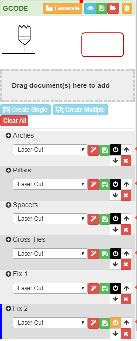
Now that we have positioned our file precisely relative to our machine origin, it is time to convert our files into actual GCODE the machine will use to cut out our parts! To do so, we need to generate toolpaths out of the paths in our file. We first need to drag the desired paths into the green “GCODE” bin lower down the column. Doing so will create toolpaths out of the paths/groups placed into the bin and group them as a single Operation. This grouping is especially useful when we move on to tips and tricks on how to optimize the cutting process. More on that in later tutorials.
As expected, we can drag and drop not just single path entities, but entire groups/parents as well which will result in all child paths/groups being selected as well:

Heck, we can drag entire document files as well!
After you have dragged the required paths/groups/files into the GCODE bin, a dropdown will appear below containing the individual operations that have been created from the paths dropped into the bin. Note that all paths dropped into the bin at the same time will be grouped into a single operation.
It is also possible to individually remove entities/groups from an operation by clicking on the trash icon next to them.
You can also add new entities/groups into an existing operation by selecting and dragging them into the existing operation like so:
The first thing to do after creating an operation is to set the type of operation. LaserWeb has a couple of preset operations we can choose from to achieve our goals. In this tutorial, we will focus solely on the Laser Cut tool as that would be the most commonly used tool for any laser cutting job. Here are the parameters for Laser Cut:
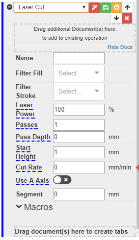
- Name – Input an identifier to keep track of what the operation is intended for
- Filter Fill – This changes the fill colour of the GCODE preview in the grid (not applicable for Laser Cut)
- Filter Stroke – This changes the stroke colour of the GCODE preview in the grid
- Laser Power – The intensity of laser for the operation (0-100%)
- Passes – The number of times the laser cutter will make a pass in the operation. Applications of this is when you want to cut a thicker material by making a cut multiple times.
- Pass Depth – How much down the Z axis should move into the material as it cuts. For laser cutters this should generally be 0.
- Start Height – How hight from the Z home position should the laser head be. This is only relevant for machines with a Z axis that can be controlled via the motherboard. This start height is also very important as it determines whether or not the material is being cut at the focal point of the laser cutter’s lens.
- Cut Rate – the speed at which the operation will be carried out. A faster rate means less time for the laser to penetrate and cut the material. However overly slow cut rates will increase the overall job time and also lead to unncessary use of the laser. As with all things a balance needs to be struck with regards to this setting.
- Use A Axis – whether or not the machine should use the rotary axis (usually disabled for standard 3 axis XYZ machines)
- Segment – this segment option can be used to simplify GCODE by literally “cutting corners” on many-sided edges by cutting across using a segment. However it is best to leave it at zero to avoid any unwanted oversimplifications of our design.
At the top of the operation, we also see a variety of small coloured buttons. They are:
- Red Magic Wand – load preset settings from a material database
- Green SD Card – save these settings into the material database
- Yellow Power Off – Deactivate this operation. Clicking on this causes the entire settings dropdown to become greyed out. The operation will not be added to the final GCODE and will not show up in the grid preview.
- Up and Down Arrows – As the operations are executed based on their order (top to bottom), these arrows allow you to order the operations as you like.
- Red Cross – This deletes operations and removes them from the list
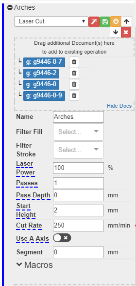
Here is a snippet of the settings I typically use for 5mm plywood on my DIY laser cutter:
Once you are done adding operations and have finalized the parameters for the operations, it is time to generate our GCODE! To do so, hit the yellow “Generate” button at the top of the box and you should see a progress bar that will gradually fill up. Once the generation process has been completed, you should now see a red overlay above your document preview in the grid. If you don’t see this, check that “Show Gcode” is checked in the visibility toggle menu.
Great! You’ve created your first GCODE file. Now it’s time to run it on your machine! To do that, you could save your GCODE out as a .GCODE file, load it onto an SD card and run it from there. However if you are using LaserWeb, you are most likely also using the Raspberry Pi server. In the next tutorial we will look at how to setup connection to this Pi server running the LaserWeb server.