In this project, I attempt to design and construct a working reflow hotplate for SMD soldering.
Why use hotplate soldering for SMD components?
Having used solder paste for SMD soldering for quite a while now, I can’t say how satisfied I’ve been with the whole experience. Oftentimes, solder paste soldering is the only way to solder small SMD packages onto a PCB, as the quantity of solder dispensed is too much and the precision too low when using a conventional soldering iron and solder wire. The most accessible way of getting started with SMD soldering is to use a hot air soldering station (which was exactly how I started off using this inexpensive station).
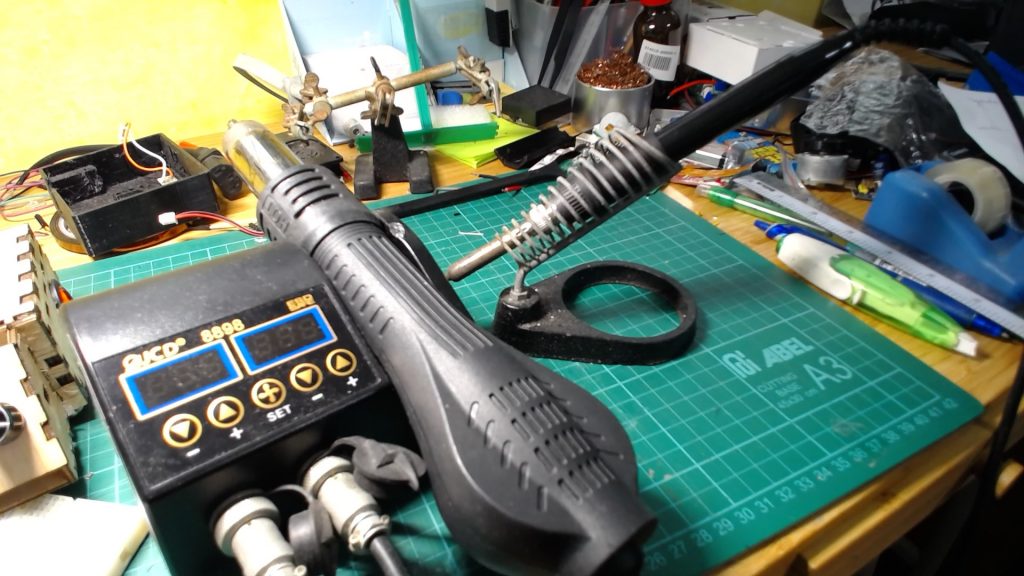
Having used hot air SMD soldering for a while, a constant thorn in the side for me was the fact that using a hot air gun to reflow the solder was both time-consuming and extremely tricky to pull off, even with experience.
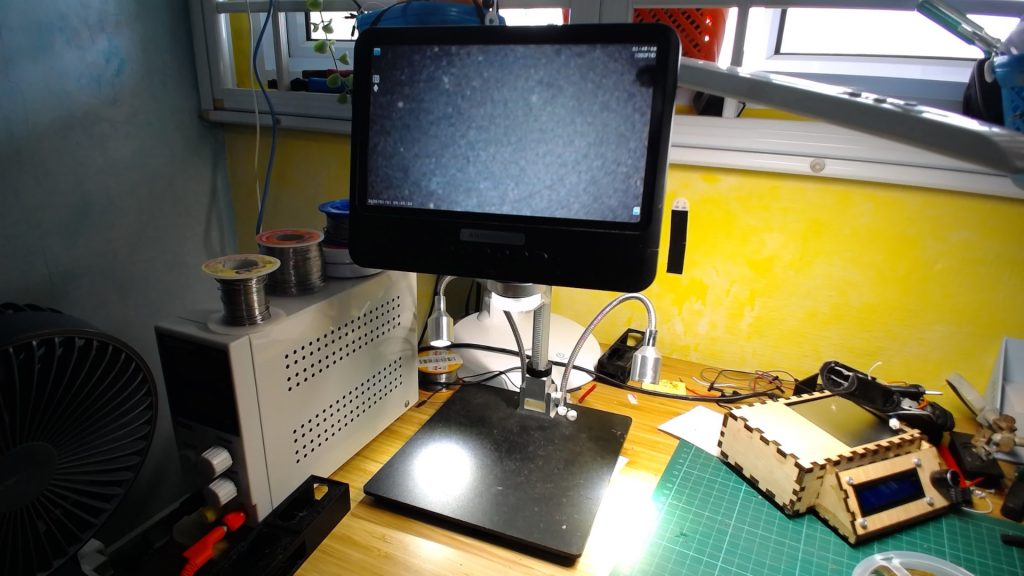
For starters, hot air soldering using a simple hot air reflow soldering station (such as the one pictured above) meant that I had to dedicate one hand to hold the hot air gun, leaving only one remaining hand to work the tweezers to position the board. Although this might not sound like a major challenge, that meant that the PCB had to be mounted securely onto the workbench as any slight movement would cause the part to shift away from the view of the electronics microscope and would involve me having to put down the hot air gun to reposition the PCB. Consider the number of times one may need to do this during even the most uncomplicated of jobs and you can see how this poses one heck of an inconvenience. Although PCB vices and holders exist, the clamps themselves would either have to be very heavy or be themselves clamped to the workbench, both of which present a challenge to the average hobbyist who is most likely working from a simple table setup. Also most of the time SMD components require fine positioning over an electronics microscope which means that large and bulky vices would not be able to fit under these relatively small microscopes
Secondly, the hot air gun itself presents a major safety hazard as the entire lower metal surface of the hot air gun reaches the preset temperatures (usually upwards of 250 degrees Celsius). Pair that with the fact that the hot air gun is often very long and unwieldy and as the need to constantly place the gun back in the caddy when not using it (to preserve the lifespan of the heating coils) and the chances of accidentally brushing against the hot zones (or touching something with the hot zones) is not very small. Having accidentally touched these regions before and gotten scalded, I was certainly looking for a safer way to do SMD soldering.
Lastly, preheating the PCB to pre-melt the solder paste was very difficult when using hot air soldering. This was due to both the fact that hot air soldering would take up one hand, making it difficult to work the solder paste syringe and position blobs of solder paste accurately on the PCB, but also because the region heat was applied over the PCB is highly localized due to the small diameter of the nozzle. Before learning about hotplate soldering, I managed to preheat my PCBs by balancing my hot air gun on a box of wires and the nozzle on a tin of flux. You can see from the image how dangerous and outright stupid this looks but the problem was there was no better way of preheating the board hands-free (perhaps a hairdryer would have worked).
What is hotplate SMD soldering?
As the name suggests, hotplate SMD soldering replaces the hot air gun with a hotplate that a PCB is placed on. By transferring heat from the bottom of the PCB to the rest of the board, the solder paste on the PCB can undergo its reflux process the PCB, and thus the solder paste and components on it.
Case Design:
The inspiration for the reflow soldering hotplate came from a video by Electronoobs on the same topic. However instead of directly using his model, I decided to redesign the implementation of the hotplate for two reasons: Firstly, I had recently finished construction of my DIY laser cutter and as such wanted to maximize the use of laser-cut parts (Electronoobs used 3D printed parts). Secondly, Electronoob’s design was a bit too tall for my liking, as I wanted to use the hotplate below my electronics microscope which did not have a very large Z clearance. As such, I went about re-designing the housing layout of the hotplate from scratch.
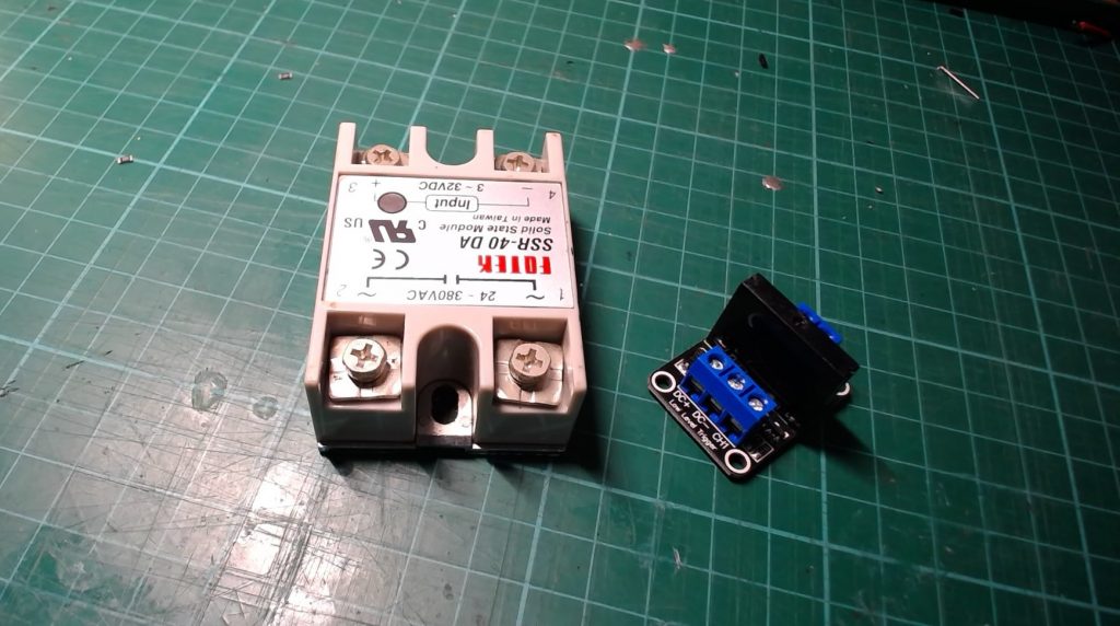
The first thing I worked on was positioning all the components relative to each other. As the small Solid State Relays (SSR) that I bought had not arrived yet, I used a Footek SSR-40DA I had lying around. However, in future revisions of the hotplate, I will be using the smaller relays due to their smaller form factor and lower cost (since the hotplate is unlikely to draw more than 2A).
Then, I proceeded to design the case around the components, all the while trying my best to optimize the enclosure to a cuboid shape so as to make laser cutting easier. Eventually, I arrived at a rather modest-looking design:
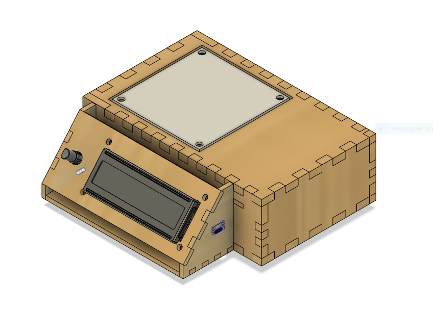
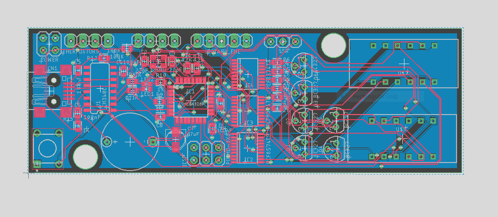
The next stage was laser cutting the various parts out of 5mm plywood and assembling the components. As the Footek SSR was rather chunky, squeezing everything into the enclosure was a challenge. This was also exacerbated by the fact that I was using an Arduino Nano with pin headers soldered and as such the form factor of the control board was also very large. This would be remedied in the future by custom-designed PCBs (with onboard ATMEGA328P) to reduce the size of the control board.
Code:
As for the code, the most time-consuming aspect was coding the Graphical User Interface (GUI) for the 2004 LCD screen. Unlike ElectroNoobs’ implementation, I wanted an LCD that not only allowed users to control the various heating modes of the hotplate but also allowed users to change key parameters on the fly (such as PID values and reflow curve setpoint temperatures). This was all in line with the idea of producing a working product that users with little coding experience could use and tweak (without ever having to touch the ArduinoIDE). However, certain parameters were still hardcoded into the firmware to reduce the coding workload (such as the time spent on each reflow curve temperature setpoint) as these parameters were deemed to be generally universal for all users.
As for the bread and butter of the code, the PID control was coded by hand for the sake of simplicity. As such the process of determining the final output value for the SSR was done in the following manner:
- At every time interval, take a reading of the temperature from the thermistors.
- Calculate the Error by substracting the current temperature from the setpoint temperature.
- Calculate the PID Output value using the below formula
- Calculate the Culmulative Error (by adding
Where Kp, Ki, and Kd are constant parameters to be determined. A common way of thinking of PID (or at least how I remember it from my time with quadcopter controls) is that Kp reacts to present (ie increasing Kp makes the controller more reactive to the current error), Ki reacts to the past (ie increasing Ki makes the controller more reactive to past or cumulative error) and Kd reacts to the future (ie increasing Kd makes the controller more reactive to future errors: over-or undershooting the setpoint).
The main aim of a PID controller is to balance responsiveness with precision. This is because a responsive setup will tend to over and undershoot a lot more due to its drastic correction to change. On the converse, a precise setup that oscillates very little about the setpoint will take very long to reach the desired setpoint as it does not make sudden or drastic corrections. Implementing a successful PID algorithm is thus about managing these two conflicting requirements and obtaining a compromise. At the moment the PID algorithm is very responsive but as a result, fluctuates wildly about the fixed setpoint. I will be conducting further tweaks and modifications to the parameters after the custom PCBs arrive (as at the moment I am unable to access the Arduino nano as it is sealed inside the hotplate case).
Safety Features:
As always safety is the number one priority, especially when it comes to dealing with high voltage or temperatures. I will break down the various safety features into hardware and software features.
Hardware:
General safety precautions when dealing with live electricity were taken such as using crimp connectors whenever possible and heat-shrinking all exposed terminals/solder joints. Additionally, I wired a 10A circuit breaker in series with the load to cut off current to the hotplate should a short occur. I was initially also thinking of adding an AC temperature switch to the underside of the hotplate. However, I decided against that as the body of the temperature switch was made out of metal, and hence placing the switch in contact with the metal hotplate would present an electrocution risk if the AC voltage somehow leaked out to the frame.
Software:
Personally, I found that software safety features were a lot trickier to implement because they would interfere with the working of the PID algorithm (as discussed above). However, I did try a couple of software features:
- Thermistor Temperature Error
Initially, I tried using two thermistors to measure the temperature of the hotplate and call an error when the two values deviated by too much. However, this failed as despite using the same values of Beta for the Steinhart-Hart equation (an equation for finding the temperature based on the resistance of the thermistors and pre-defined constants), the thermistors consistently reported readings that would deviate by a lot at high temperatures (we’re talking about 50 degrees or so). As such I just decided to abandon the idea and work with only 1 thermistor.
I also tried implementing a thermal runaway feature. The basic idea of such a feature would be to call an error when the PID value was increasing (thereby meaning that the SSR was pumping current into the hotplate) but the temperature was not increasing. This situation could mean two things: firstly, for some reason, the control board is powered but the heater plate is not (this could be during testing on USB power or if the hotplate fails open). Thus the control board “thinks” that the heating is insufficient and tries to correct this by pumping up the PID output. This is the less severe of the two possibilities as even if no thermal runaway is called, the heater cannot possibly pose a fire threat as it is offline. However, a worse possibility (and one which essentially necessitates the need for thermal runaway protection) is that the thermistor has come loose from the hotplate and hence is no longer registering the increase in temperature. This poses a massive safety risk as the hotplate is online and will be continuously pumped with ever-increasing amounts of current, reaching very high temperatures and possibly starting a fire.
I implemented thermal runaway protection using the following logic chain:
- Every set interval, check the change in PID output (this is done by saving a variable called PID_Output_Last every end of a cycle and comparing the current output with this output)
- Also check the change in temperature output (in a similar fashion as 1.)
- IF PID output increases by a value greater than a set amount AND temperature does NOT increase by a value greater than a set amount, call thermal runaway.
This essentially checks if the PID Output actually causes a change to the measured temperature of the hotplate (ie that the cause and effect relationship exists). However, there are a few problems.
- It is possible that if a short interval is used for this runaway checking, the temperature may not rise by a value greater than the set threshold despite a increase in PID output that exceeds the PID threshold, thus causing a false positive runaway error.
- If a long interval is used, thermal runaway may not be caught in time if and when it happens, and the change in PID Output and temperature values may oversimply the situation: consider a graph PID Output/Tempreature against time:
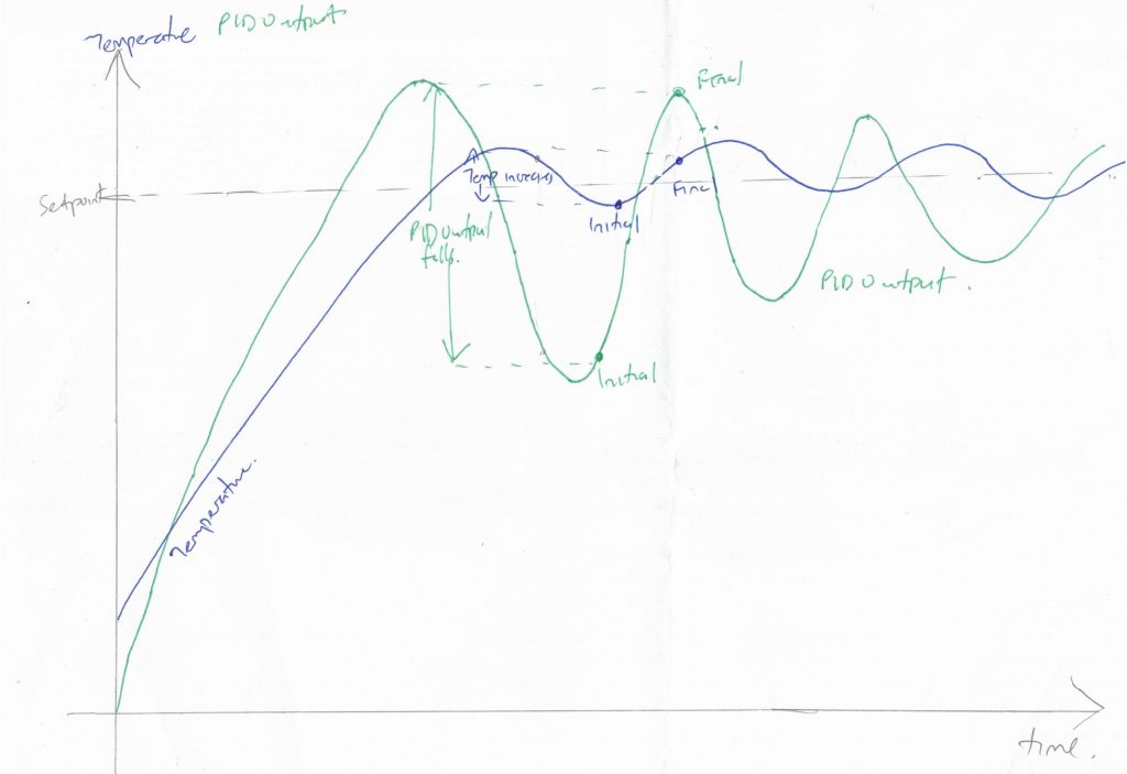
The above image depicts a situation in which the value of Kp is large and hence the PID controller is prone to over/undershoot the setpoint. As there is a noticeable time lag between the PID Output changing and the thermistors registering an increase in temperature, it is possible for the thermal runaway program to unwittingly call a false positive due to the PID Output appearing to be increasing (due to the temperature initially overshooting, thus bringing the PID Output down low) at a much larger rate than the temperature (due to the long time taken for the temperature to rise due to the slow rate of thermal transfer). Of course, the following example is heavily exaggerated and in reality, the PID algorithm should be designed to prevent drastic fluctuations in temperature and PID output values.
From my experiments with the initial design, I found that the first situation was a lot more likely than the second, and as such, I chose a relatively long interval for the thermal runaway check (~10s). Off the cuff, a possible modification that would reduce the probability of false positives would be to only start the interval timer when the PID Output increases. I shall see if this reduces the failure of the thermal runaway protection feature as I continue to modify and upgrade the design.
Performance and Real-Life Testing:
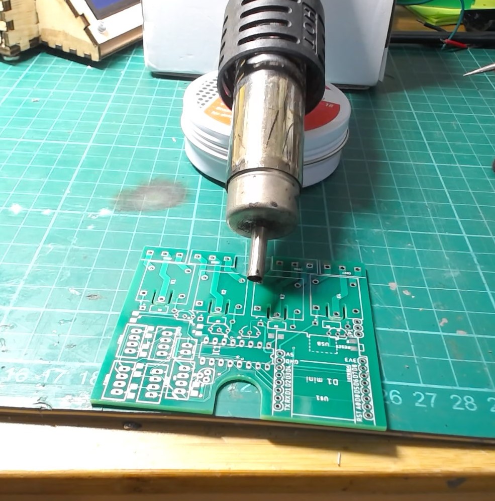
I tried the hotplate out on an Arduino clone PCB I was designing and I couldn’t have been happier with the results. I think it would be best to let a video do the talking:
Concluding Thoughts:
Having experienced SMD solder paste soldering by hot air gun, I can really begin to appreciate not just the amount of time this will save me but also the increase in cleanliness, structural integrity, and overall quality of solder paste joints this new technique will grant me.
As there is still a lot of refinements to be made to this project (most notably the changing of the SSR and the custom PCBs), I this post will most likely be updated in the future with the latest developments.