GitHub Repo: https://github.com/RCPilot1604/Player-Piano
Last year while scrolling through the internet, I came across a rather interesting project – a piano capable of playing itself. I immediately decided that I needed such a device but instead of replicating the design already available on the internet, I would design one myself from scratch.
From my extensive research regarding DIY player piano builds, I have come across two designs:
- Brandon Switzer’s Project (link here)
Control Board: ESP32 (for receiving MIDI over BLE and handling note scheduling) and Arduino Pro Micro (for controlling hardware)
Demux IC: 74HC595 shift registers (with PWMShift library)
Solenoid Control: TP120 Darlington NPN BJTs - Japhillips87’s Project (link here)
Control Board: ESP32
Demux IC: PCA9635 I2C PWM LED Controller
Solenoid Control: IRL540/520N N-Channel MOSFETs
It is worth noting that the “algorithm” (software) used in both projects are similar, as Japhillips87’s project uses a modified version of Brandon’s original C++ code (modified to use PCA9635 instead of ShiftPWM over shift registers).
Given these two existing and working examples, I nonetheless embarked on designing my own player piano (software and hardware) for the following reasons:
Hardware:
- Similar to Japhillips87’s design, I was not too fond of having 2 MCUs instead of one.
- I inherently prefer MOSFETs for high-current switching applications over BJTs (even if they are Darlington).
- I wanted to fabricate a proper PCB instead of relying on unreliable breadboard (as in the case for Brandon’s project). However, Japhillip87’s PCB did not suit my liking for the following reasons:
– Direct use of the ESP32 WROVER/WROOM Castellation SMD chipset instead of the DIP development kit used by Japhillip87’s design.
– Expansion IO pins utilizing the plethora of GPIO on the ESP32
– In-built power supply (buck converter) to supply the ESP32 with power (in the case of Japhillip87’s design, power had to be supplied over a USB cable to the WROOM/WROVER ESP32 dev kit).
– Physical layout of the MOSFETs. In Japhillips87’s design, the MOSFETs are arranged in two rows. I wanted the MOSFETs to be positioned all in a single row so that I could more effectively isolate the high current section/high voltage segment of the PCB from the low current/low voltage segment.
– Form factor. Due to me having JLCPCB USD$8 vouchers (for using EasyEDA) [this promotion has since been discontinued 🙁], I was limited to a 100mm by 100mm PCB outline (in order to enjoy discounted rates on my PCB order). - I wanted to make some upgrades (after V0). These upgrades will be covered in the V1 section of the post.
Software:
- I did not understand Brandon’s code at all. This was likely due to my relative inexperience in OOP.
- I wanted to add more features to the player piano:
– Rotary Encoder with LCD to change settings on the fly without having to modify the source code and re-flash the board
– EEPROM to store settings
– Future modifications such as converting the BLE communication protocol to serial (by having a dedicated player piano server running on an attached raspberry pi).
With this in mind, I proceeded to begin my design of my player piano.
Hardware Design:
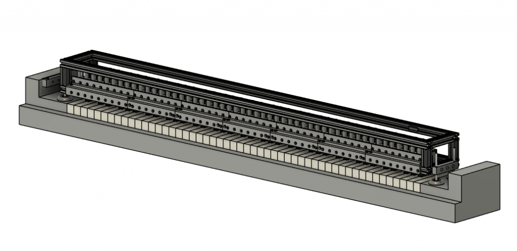
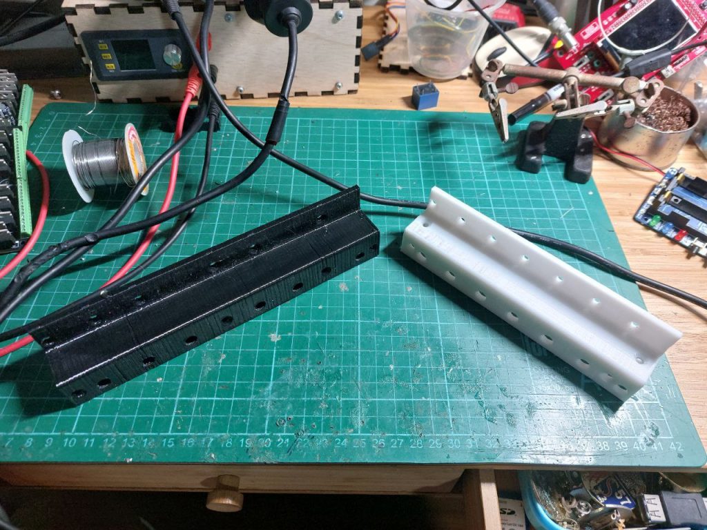
For the choice of solenoids, I followed the designs of both Brandon and Japhillips87, opting for the JF-1039B 25N solenoids. Therefore, the main difference between my design and their design was in the frame. I wanted a frame that was easy to build and lightweight enough to be transported around, as I anticipated that I would have to move the setup on and off my piano for various tuning/repairs. Therefore, the frame consists of a simple 2020 aluminium extrude structure with 3D-printed mounts for the solenoids.
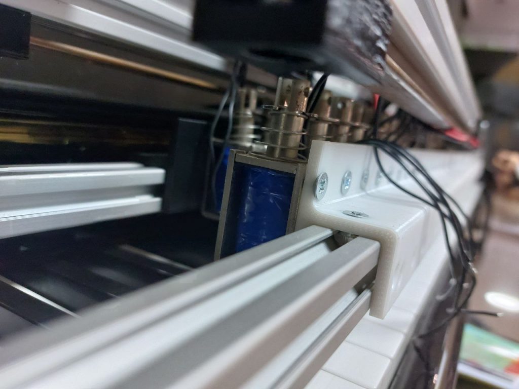
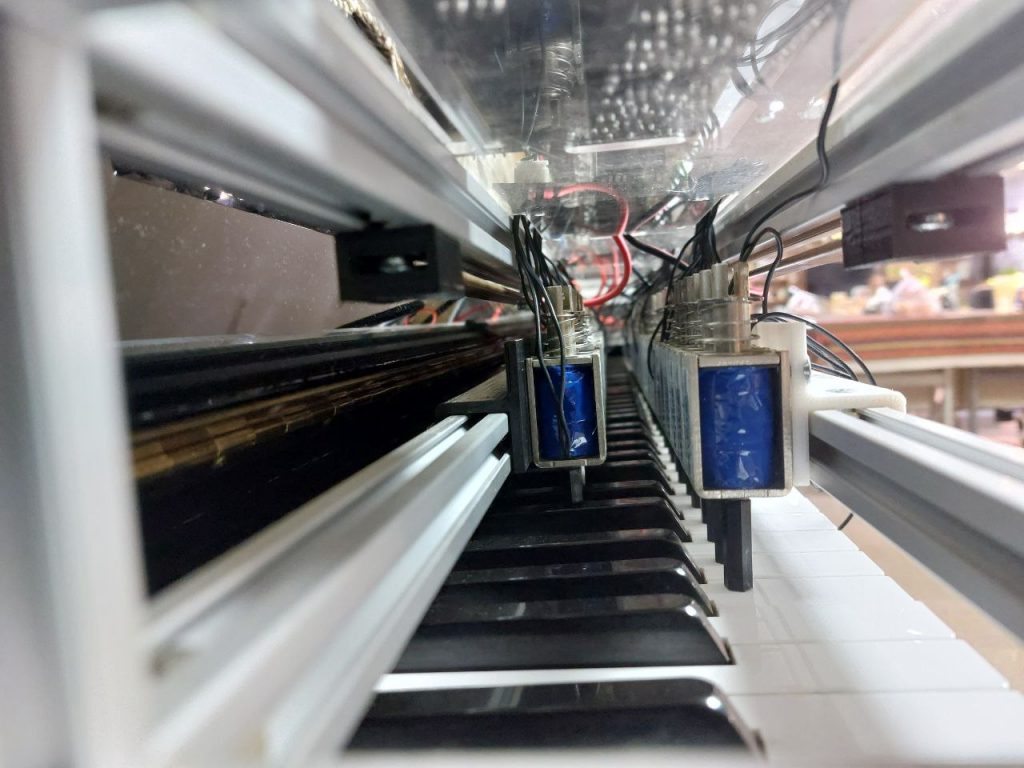
To extend the plunger shaft of the solenoids and to allow them to contact the piano keys, I purchased 12mm and 25mm (for black and white keys respectively) plastic M4 standoffs that I directly screwed into the base of the M4 plunger threaded shafts of the solenoids.
For the electronics hardware, I designed a PCB in EAGLE (full schematics and board files can be found in the GitHub linked to at the top of the post):
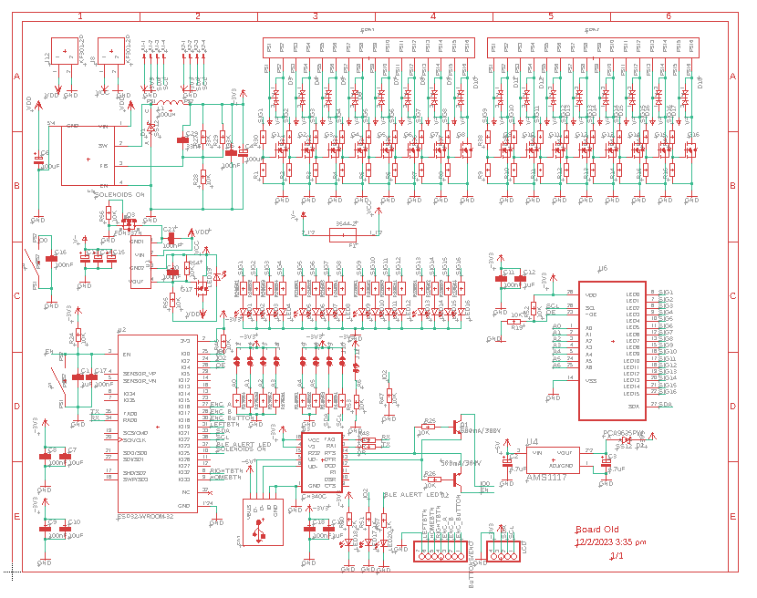
The schematic design is rather straightforward, with a few functional blocks:
- ESP32 with required pullups/capacitors as well as the appropriate USB-Serial circuitry (CH340C with the IO2 and EN transistor circuit to toggle BOOT and RST pins).
- Power supply for ESP32 (XL7005A buck converter configured to supply 3v3)
- PCA9635 I2C PWM LED Driver
- IRL540N N-Channel MOSFETs and BYQ28E Flyback Diodes (the choice of these components was influenced by Brandon’s and Japhillps87’s designs).
- B1212 Isolated 12V power supply to switch a CSD19505 N-Channel MOSFET. This was intended to serve as a cutoff MOSFET for the entire solenoid circuit. The goal of this was to ensure that the solenoids would only receive +24V power when the ESP32 and PCA8635 were fully set up. This was ditched in V2 due to the unreliability of the circuit in favour of a mains relay to switch the 24V PSU on and off.

Routing this circuit was a nightmare due to the “streams” of signal lines that had to run across almost the entire circuit. Moreover, I wanted to isolate the +24V (“High” voltage) elements of the circuit (solenoids, N-mosfets etc) from the +3V3 (“Low” voltage) elements of the circuit, resulting in me having even less space to work with.
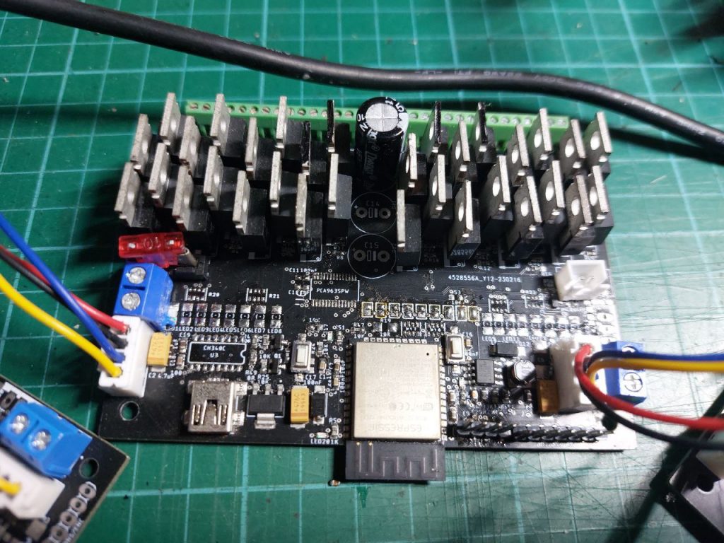
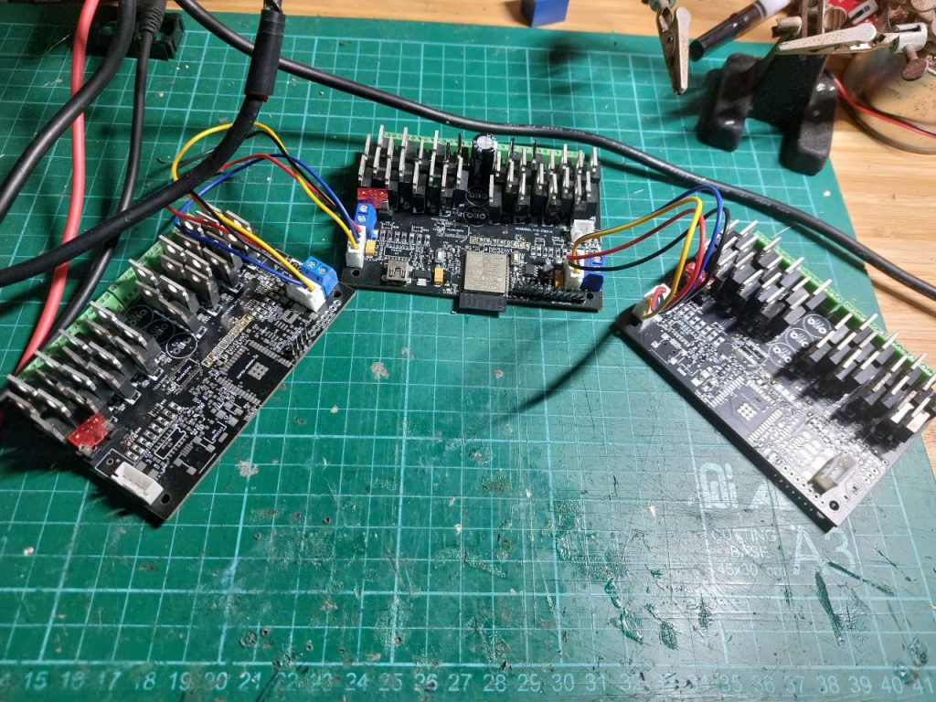
Each PCB could accommodate up to 16 solenoids. Therefore for a piano with 88 keys, 6 boards were required (5 * 16 + 1 * 8). However, since the PCA8635 could take one of up to 128 programmable I2C addresses, only 1 ESP32 I2C master was required to control all 6 PCBs. The PCBs were thus daisy-chained using 24AWG wires via JST-XH (2.54mm pitch) connectors.
Software:
As a form of personal learning, I decided to challenge myself by writing the software for this player piano in OOP rather than the functional paradigm I was accustomed to (typically, I use functional programming for my smaller ArduinoIDE/ESP8266 projects). As this was just before entering University, I did not have any formal C++/OOP experience but nonetheless I was up to the challenge.
The program was organized into the following files (.h and .cpp):
- main.cpp (formerly Player_Piano.ino before the PlatformIO migration) contained the main program function [void loop()] and would serve as the entry point for the entire program.
- Note.cpp/.h served to declare the Note class that represents each of the 88 notes of the piano. In the main loop, a vector of 88 notes are created, representing the keyboard. Each individual note has its own attributes that are used to store unique note settings such as max_velocity, min_velocity, midi_id etc, as well as the current noteState and the lastScheduledState. Structuring each note on the keyboard as an individual object thus allows customization of each note which is crucial for tuning the player piano to ensure that the loudness of each key is normalized.
- Commands.cpp/.h served to declare the Commands class. In each note object, a vector of Command objects are stored. This vector of commands thus represents the upcoming commands for that particular note.
- Settings.cpp/h serves as a “global” object that stores all the settings of the player piano. Although global variables could be used I wanted to ensure some degree of encapsulation and access control.
In general, I aimed to make the entire process of fetching commands as structured as possible to reduce the time spent searching for existing commands. This is because not only must the software be able to play the notes as they are sent by the midi host (BLE Midi device which is usually a mobile phone running a midi player like Synthesia), but the software also needs to be able to reject impossible/sticky notes.
Algorithm for Rejecting “Impossible”/Sticky Notes:
Schedule ON:
Whenever a note is scheduled ON, the algorithm first checks the current and last scheduled state of the note. If it is currently ON and its last scheduled state is also ON, this means that there exists another command that wants to turn our note on before the current command at hand. This means that we need to first check to see if the earlier command can successfully activate and deactivate before our next command arrives. If so, we can schedule a “just-in-time” activation of our current command. Else, we check to see if there is enough time to modify the earlier command to be a bounceback ON command (where the solenoids activate with a much higher initial acceleration to “rebound” the key, achieving higher deactivation timings). If none of these are possible, the algorithm simply ignores the latest command as impossible.
If the current state is ON and the last scheduled state is OFF, the algorithm checks if the earlier OFF command has enough time for deactivation and reactivation. If so it brings forward the deactivation for a “just-in-time” deactivation and reactivation. If not then it simply deletes the previous OFF command (note stays ON the whole time).
Similarly, if the current note state is OFF and the last scheduled state is ON, the algorithm checks if there is sufficient time for the earlier ON command to execute, and if a bounceback is required. If both options are unavailable, we simply ignore the newest ON command, letting the previous ON command take precedence.
Schedule OFF:
Whenever a note is scheduled OFF, the algorithm first checks the current and last scheduled state of the note. If it is currently OFF and the last scheduled state is also OFF, it ignores the latest command as it is an unnecessary OFF command for a note that is already going to be scheduled to be OFF.
Else if the last scheduled state is ON, the algorithm checks if there is enough time to schedule the activation and deactivation of the note. Similar to when scheduling ON, it checks if it is possible to modify the earlier ON command with a bounceback. When that fails, it then deletes the previous activation command (note stays OFF the whole time).
If the current state is ON and the last scheduled state is OFF, the algorithm ignores the latest command as it is an unnecessary OFF command. If the last scheduled state is ON, the algorithm checks if there is enough time for the ON command (with and without bounceback), and if there is insufficient time to schedule a bounceback, it deletes the previous ON command (the note stays OFF).
This algorithm is rather confusing as it essentially is a swamp of nested conditionals. Hopefully with the extensive comments that have been included in the code, anyone wishing to modify/verify the code will be able to do so.
To test/verify the behaviour of the algorithm, I created test midi files that would schedule notes under the specific test conditions (as mentioned above). I would then verify that the algorithm would exhibit the desired behaviours. These test files were extremely helpful for debugging the code (together with a copious amounts of print statements). I have linked the files as well as the Excel sheets used to generate these files here.
Areas for Improvement for V1:
- I am still in the midst of testing my homebrewed code. However as I wanted to first single out and squash any errors in the hardware (electronics), I flashed the ESP32 with Japhillips87’s code first to test the Player Piano. This allowed me to begin work on V2 without having to wait for my homemade code to be fully tested and debugged.
- There are a couple of hardware issues that have played V1:
– Lack of rigidity of the 2020 frame. Due to the sheer strength of the solenoids, the entire frame is flexed upwards (against the weight of the solenoids and frame) when 5 or more keys are pressed. This then causes the solenoids to be lifted away from the keyboard and thus causes them to bottom out, creating undesirable clicking noises. Additionally, this violent heaving of the entire structure causes the mechanism to rock about the keyboard which is rather dangerous as there is a real chance of the entire machine simply jumping off the keyboard and onto the floor.
Remedy: replace 2020 profiles with 2040 profiles for greater strength and ridigity (V2).
– Audible clicking noises caused by the aforementioned bottoming-out but also due to the plastic standoffs impacting the base of the solenoids on the return stroke.
Remedy: Rethread all solenoids with longer M4 threaded rods instead of using standoffs. This way there will be no contact between the plunger shaft and the solenoid body.
I am currently working on V2 and will be posting a separate post when the modifications are finished.