Code is available at this GitHub link.
Recently, someone on the Player Piano Discord that I am part of (yes, I am in the process of designing and building a player piano) sought advice as Brandon’s Player Piano Code was not working for him (to be specific, he was unable to connect to the ESP32 via Bluetooth using his code). After reading through Brandon’s code, I observed that he was using a different library from the one myself and another fellow player piano builder, japhillips87, were using (BLEMidiTransport).
However, as he had already bought all of the hardware (comprising 74HC595 shift registers, breadboards etc) except the solenoids, he wanted to use his existing hardware as far as possible and avoid purchasing more. To solve his problem, I would thus have to modify Brandon’s code to use the tested BLEMidiTransport library or japhillip87’s library to use 74HC595 shift registers. I decided to opt for the latter because Brandon’s code was difficult to read and relied heavily on Midi Messages being sent and parsed by the Arduino Pro Micro. Moreover, I had recently coded my own software for my player piano by referencing japhillip87’s code and as such, I was more familiar with how his code worked and would thus be better able to integrate these new modifications into his code.
The main problem I encountered when trying to integrate shift register PWM into the ESP32 was that there simply weren’t a lot of libraries out there catered to this ESP32. Most of them were designed for ARM architecture (specifically the ATMEGA line of microcontrollers) and digging into their source code revealed that they utilized a lot of manual register setting to minimize the size of the program and improve efficiency. However, this meant that these libraries would simply not work with the ESP32 which had a totally different architecture and set of registers.
To their credit, I did find one ShiftPWM library for the ESP32. However, I was unable to get it to work as I couldn’t really understand how the code worked and the documentation was sketchy. As such, I decided to challenge myself by coming up with a library myself.
The first thing I did was reference existing ShiftPWM libraries originally meant for the ATMEGA boards. One great example of such a library is Timo Denk’s ShiftRegister PWM Library. He provides superb documentation and explanation of how his code works and this was a great aid in my understanding and adapting his implementation to the ESP32.
How a ShiftRegister Works:
Before we can start implementing PWM, we should familiarize ourselves with the basic operation of a shift register (74HC595). There are many great articles about this subject all over the web, but the one I found most useful (as with many of their articles) is LastMinuteEngineer’s write-up. It includes detailed images of pinouts, clear explanations, a gif depicting the operation, and even code for using the shift register (albeit not with PWM).
A shift register can be thought of as a conveyer belt: when the clock pin is pulsed, the conveyer belt is moved down one step, and the logic level (HIGH or LOW) on the data input pin is placed onto the “newest” position of the conveyer belt. By toggling the clock pin and inputting a series of bits (HIGH or LOW) at the data input pin in a particular pattern, we can thus create a pattern of these bits on this imaginary conveyer belt. Then when the latch pin is pulsed, these bits on the conveyer belt are “presented” on the output pins (A0-7), which can be used as digital outputs to various things (most commonly, LEDs). The GIF from Last Minute Engineer’s write-up most effectively explains this process:
PWM on a shift register is most usually achieved via the OE pin (enable pin), that disables the outputs when pulled high. By supplying a PWM signal to this pin, we can apply this PWM signal to all the outputs (as these outputs will turn on and off to the same PWM frequency as the OE pin). However, an immediately obvious caveat is that all 8 outputs will share the same PWM frequency and duty cycle. This isn’t a problem if we want a uniform brightness for a series of individually-controlled LEDs. However, in the case of our player piano, we want to be able to set the velocity (and therefore PWM) of each note individually. This, therefore, makes using the OE pin insufficient.
Achieving Individual PWM:
Since PWM is essentially toggling an output on and off repeatedly, varying the duty cycle (or fraction of time spent on) to achieve different “levels”, we would need to be able to individually set each output of a shift register to either ON or OFF at x times per second, where x is the PWM frequency. As such, a pretty obvious idea is to create a long “list” of the states of all the outputs at each interval (1/x second interval), and quickly cycle through this list every second, shifting out the states to the corresponding shift register. From each individual output’s perspective, the output will be toggled ON and OFF to a duty cycle determined by how many “ON” and “OFF” commands are scheduled in the “list”.
As such the size of our array can be thought of as:
Size (in bits) = Number of Shift Registers * 8 (each Shift Register has 8 outputs) * Number of “levels” (aka PWM resolution)
We could create a 2-D array with one axis being the registers and the other being the “levels” (or PWM sequence), but in Timo Denk’s library, he combined these two dimensions into one (by indexing each bit as array[StepNo + shiftRegNumber * TotalNoOfSteps]. Visually, his array can be represented as follows:
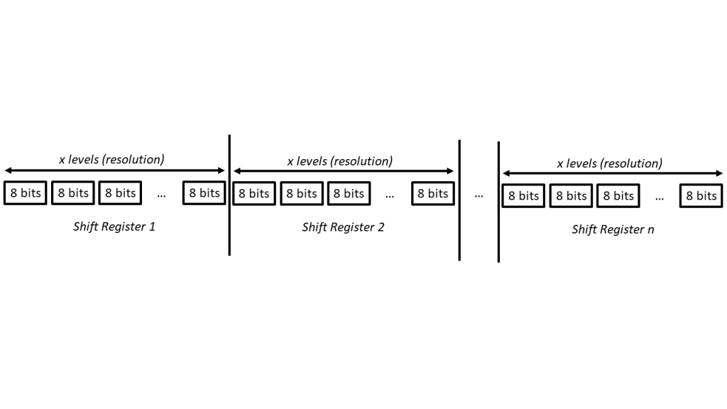
I personally found this arrangement to be a bit weird and was a lot more comfortable with arranging the bits by shift register first followed by resolution as shown:
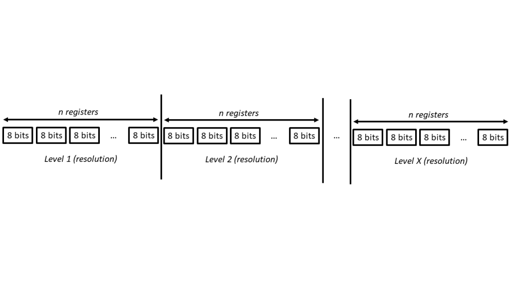
Perhaps there is some optimization gained from arranging it the way Timo did, but I don’t think there is a major difference.
With the array structure clearly defined, what was left was to code the set function to set the sequence of 1s and 0s according to the duty cycle. The idea would be to iterate through the “levels” in the array and set a 0 if the PWM value supplied was smaller than the current “level” and a 1 if it was greater. In that respect, Timo Denk did an ingenious job of creating a bitwise operation that would perfectly achieve this goal. His operation is as follows:
array[index of register at corresponding levelindex of register at corresponding level
It took me a while to understand how it actually worked, but when I finally understood it, I was amazed at its simplicity but effectiveness. I will break down the operation into bite-sized chunks, starting with the operation that comes first (in the bitwise order of operations).
1. (-(value > t) ^ array[index of register at corresponding level])
In -(value > t)
To see how this works, we first have to understand how C++ handles negative numbers in binary – using 2’s complement. There are many good articles explaining how this works, but the process of representing a negative number in binary follows these steps: first invert the bits, then add 1.
Assuming (value > t)-(value > t)
Assuming (value > t)-(value > t)
Now we have 00000000/11111111, we compare this to array[index of register at corresponding level
To see the outcome of this operation, let’s consider the truth table:
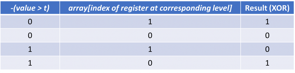
(-(value > t) ^ array[index of register at corresponding level])2. & (1 << (pin%8))
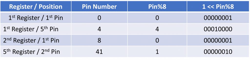
Since the pin numbers are from 0 (first pin) to number of registers * 8 – 1 (last pin), pin%8 will give the pin number of that particular register aka the position of the bit to change on that register. The left shift (<<) command thus moves 1 in 00000001 n number of times to the left, where n = pin%8. Hence if pin is divisible by 8, the register selected is 000000001. If pin divided by 8 gives a remainder of 1 (pin%8 = 1), the pin selected is 00000010, so on and so forth. Since the remainder of pin / 8 can be thought of as how far away the pin is from the nearest 8th pin (or 0th pin/first pin [remember, first pin is 0, last pin is 7]), left shifting by pin%8 places the 1 at the position of the pin. A few examples may help illustrate how this works:
The AND (&) command then sets all other bits to 0 other than the bit at the position corresponding to the selected pin. This hence acts as a filter that sieves out the selected pin, ignoring all other pins. When coupled with the XOR (^) operation in 3., this effectively preserves the other bit as 0^0 = 0 and 1^0 = 1 (bold represents the other bits which could be 1 or 0 and underline represents the result of the & operation which can only be 0 for the other bits).
3. array[ index of register at corresponding level
Since the & (AND) operation takes precedence over the ^ (XOR) operation, the order of operations is actually as follows:
array[ ^index of register at corresponding levelarray[index of register at corresponding level [(-(value > t) ^ array[index of register at corresponding level
To simplify, we can effectively remove the & (1 << (pin%8)) as we have already ascertained that it serves the purpose of filtering out the pin/bit we are interested in setting by setting all other bits to 0.
Hence for a single bit,
array[ ^index of register at corresponding level] = array[index of register at corresponding level] [(-(value > t) ^ (a byte from 0-7 which represents the pin we are setting)];
Now let us consider a final truth table to see how this operation achieves the goal we started out with, namely to iterate through the “levels” in the array and set a 0 if the PWM value supplied was smaller than the current “level” and a 1 if it was greater.
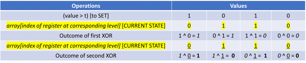
As mentioned in 2., the XOR (^) command also serves the purpose of preserving the existing value of bits we are not interested in modifying. This is because the AND (&) operation sets these bits to 0 and the final XOR (^) operation will simply just carry the existing bit over to the final result [0^0 = 0 and 1^0 = 1 (bold represents the other bits which could be 1 or 0 and underline represents the result of the & operation which can only be 0 for the other bits)].
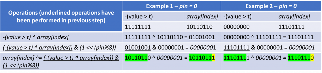
Let us consider the following full example to see how it all comes together.
With the set function out of the way, it was then time to code the update function. This function was a lot simpler as all it had to do was to iterate through our array and shift the values out sequentially in descending shift register order (since the first bit shifted in will end up right at the end of the daisy chain). The function also would iterate through the PWM levels every time the update() function was called. This was achieved through a counter variable that was incremented every time the update() function was called and would reset when it hit the maximum value.
void ESP32ShiftPWM::update(){
int offset = currentResolution * registerCount;
for (int i = registerCount - 1; i >= 0; i--){
ESPShiftOut(commands[i + offset]);
}
toggleLatchPin();
if(++currentResolution == resolution) currentResolution = 0; //reset the current resolution before it overflows the resolution
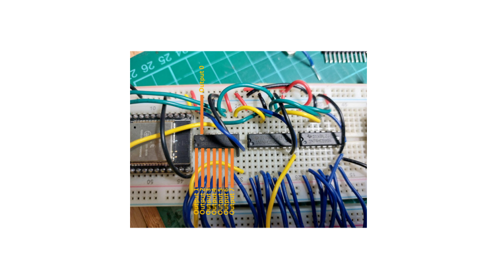
}Then I modified Timo’s ShiftOut function since for my implementation the order of bits was reversed (this was likely due to the way I oriented my shift registers and wired them up to LEDs on my breadboard):
The last step was to set up the clock to periodically call the update function. For that, I followed this guide to set up an interrupt on one of the 4 ESP32 hardware timers. The code for that is rather straightforward:
hw_timer_t * my_timer = NULL;

void IRAM_ATTR onTimer(){
  sr.update();
}
void setup() {
  // put your setup code here, to run once:
  Serial.begin(115200);

  my_timer = timerBegin(0, 80, true);
  timerAttachInterrupt(my_timer, &onTimer, true);
  //since we want the interrupt to be called at (freq)Hz, we need to set the alarm to fire every 1/(this->freq) s = 1/(this->freq)* 10^6 ticks
  timerAlarmWrite(my_timer, 1000000 / (FREQUENCY), true); //set the value in the brackets to be the frequency in Hz
  timerAlarmEnable(my_timer);

  sr.begin();
}
And with that, I proceeded to test the library:
What I was most interested in was the maximum attainable PWM frequency. The ESP32 has a maximum clock frequency of 80MHz, and we can specify a pre-scaler in the my_timer = timerBegin(0, 80, true); function call. Here we set the pre-scaler to 80 which gives us a working frequency of 1MHz.
We can further reduce this frequency in the timerAlarmWrite(My_timer, 1000000 / (FREQUENCY), true); call. In the second argument, we can specify the period (in microseconds) for the alarm to be called. I set this value to be 1000000 / FREQUENCY (in Hz) to reflect the frequency of the clock.
However, this is not the actual PWM frequency that is output on the shift register. A quick test with the trusty Oscilloscope will show that the PWM frequency is a lot lower than expected. For this test, I set the frequency to 100KHz but I instead see a measured PWM frequency of only 392Hz:
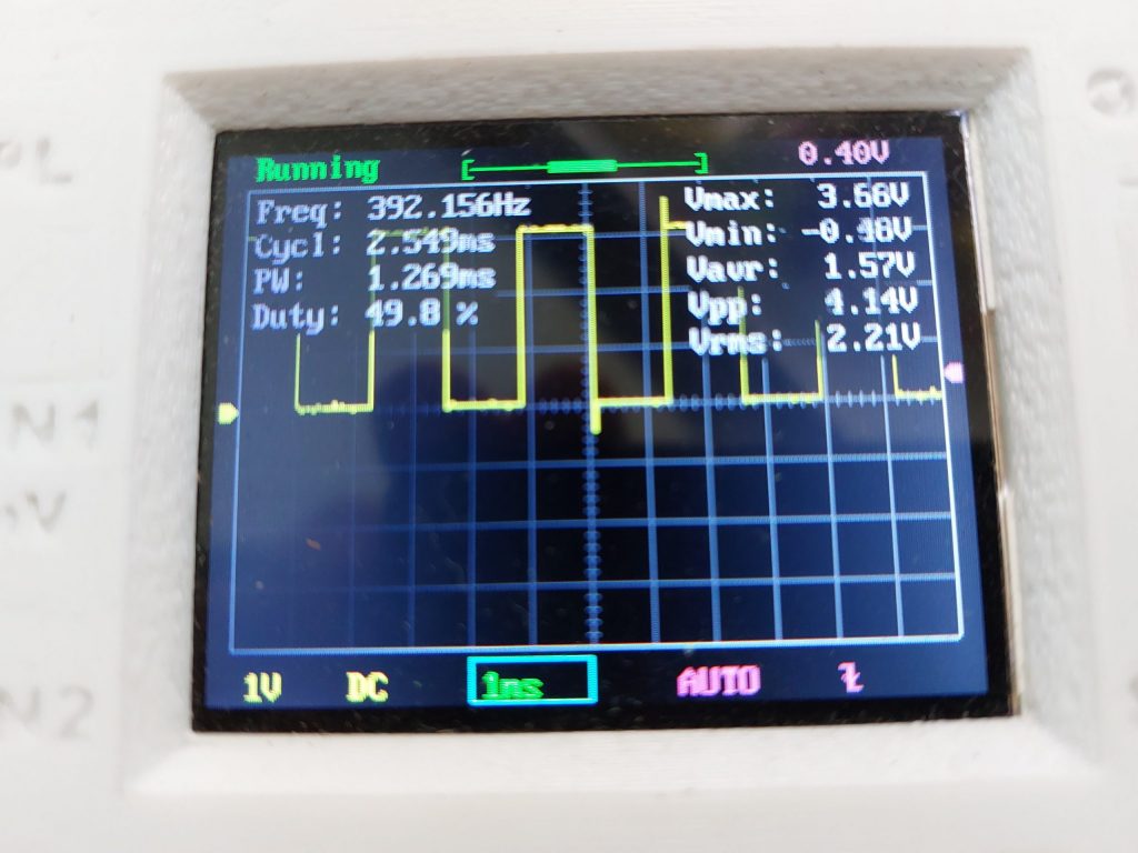
The reason is that although the update() function is called every 1/100KHz seconds, it takes resolution number of updates before the full PWM waveform can be generated. Since the resolution is set at 255, the PWM frequency would be 100KHz / 255 = 392Hz.
Hence to increase the PWM frequency, we could either increase the base frequency (by decreasing the argument to timerAlarmWrite() or decrease the resolution. However, experimenting with the ESP32 has shown me that the maximum frequency at which update() can be called is around 100-200KHz, beyond which the ESP32 cannot handle the processes fast enough (remember that update involves iterating through a resolution * no of Shift Registers large array to shift out the individual bytes). Hence it is very likely that 392Hz is the maximum frequency that can be achieved with 255-level (8 bit) resolution.
For LEDs, 392Hz is more than sufficient for creating dimming effects (50Hz is typically used since the sampling rate of the human eye is around 30Hz). However, for controlling inductive loads like motors, 392Hz is woefully inadequate (DC motors are typically pulsed at 5-20KHz). Low frequencies induce a lot of current ripple (caused by the flyback of the motor among other things). Specifically for this project, pulsing the solenoid at anything below 1KHz induces an irritating buzzing noise and causes the flyback diodes to get substantially hot).
As such although this ShiftPWM library for the ESP32 is functional, it is unlikely to be a good idea to use it for controlling solenoids for a player piano due to these limitations. The member on the Player Piano Discord is much better of using a dedicated PWM driver IC such as the PCA9635 with a PWM frequency of 97KHz.
Nonetheless, it was a good learning experience for me which exposed me to bitwise operations and the operating principles of shift registers.