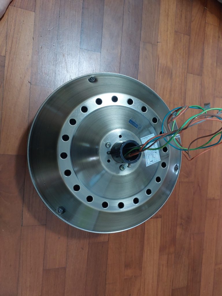
Recently, my family decided to replace the faulty ceiling fan for good. As such, I was able to take it apart and see how it actually worked. As I was still unsure about the function of the various capacitors (and whether the UNKNOWN capacitor was actually a starter capacitor), this opportunity allowed me to clear any doubts once and for all.
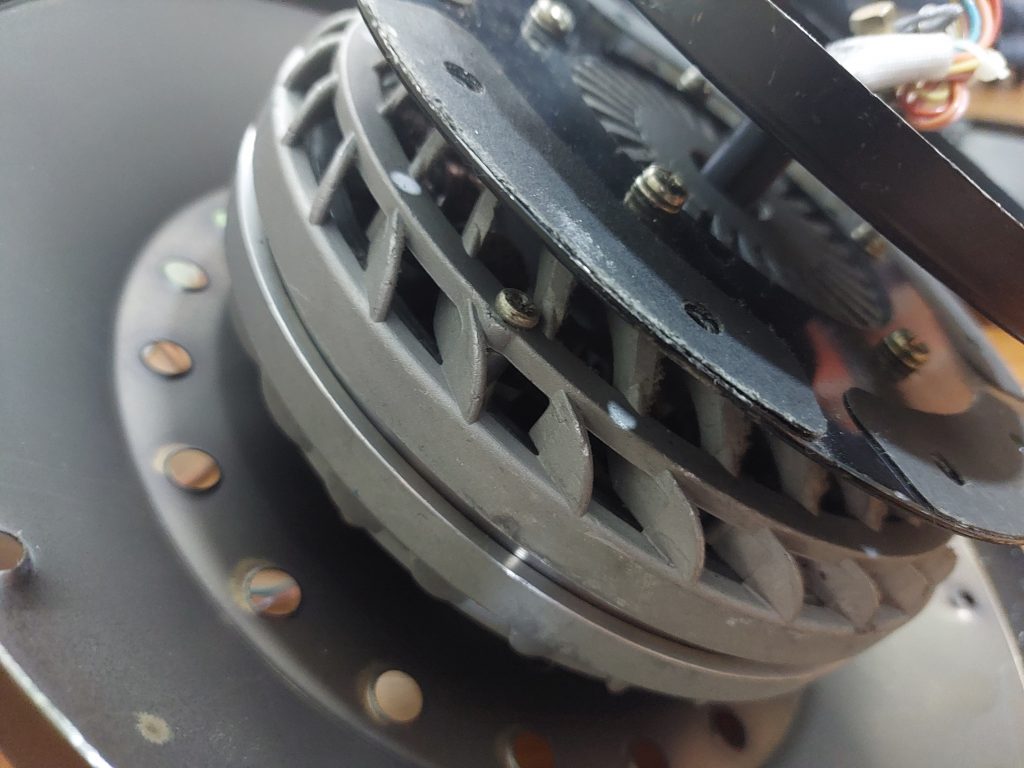
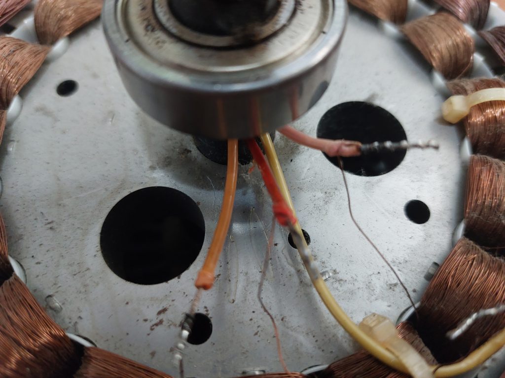
It took me quite some time, but I was eventually able to pry open the metal cage containing the coils.
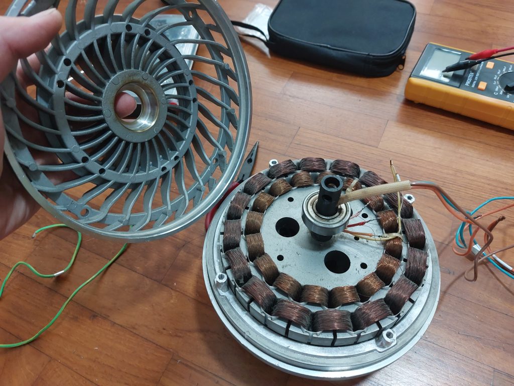
Upon closer inspection of the windings, I realized that there were two main windings: an outer and an inner coil. Moreover, the windings were each connected to their own unique wires that ran into the center shaft of the fan.
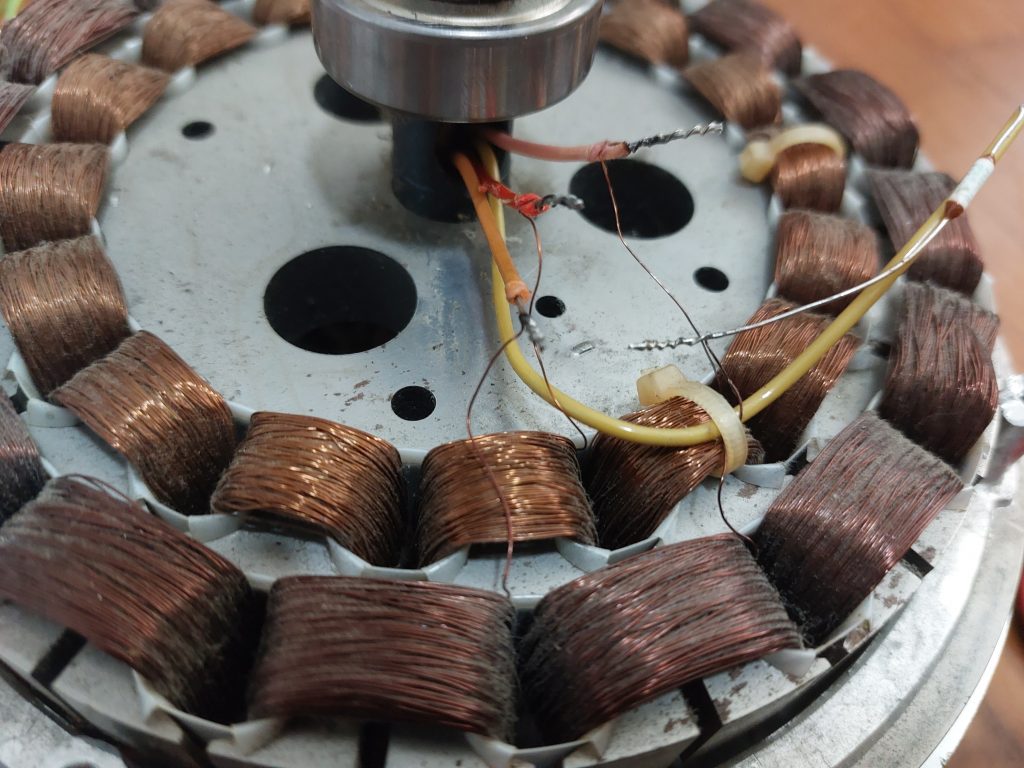
What was also interesting was that from the pictures, we can see that the coils of the inner winding sit “in between” the coils of the outer winding, similar to the following diagram:
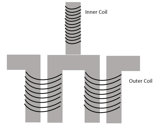
This was a tell-tale sign that the relationship between the two coils was that one was a starter and the other was the main coil. By staggering the current to the coils such that when one coil was at its maximum the other was at 0, a “moving” magnetic field can be created, inducing motion in the fan. Hence, this was sufficient evidence to me that a starter winding was present and thus there would be a need for a starter capacitor to phase shift the current in the starter winding by 90 degrees with respect to the main winding.
I then proceeded to analyze the connections in the fan connectors using a multimeter, and derived the following results:
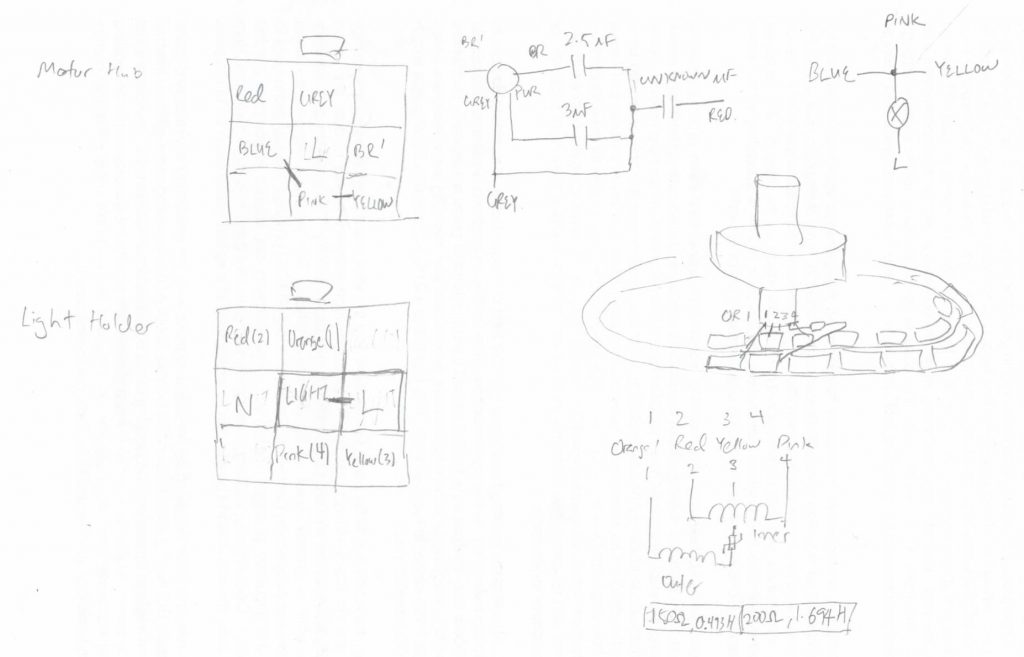
As mentioned in the previous post on debugging the ceiling fan, there are two connectors in question: the female end that is attached to the light fixture and the male end that goes into the fan’s main body (motor hub). They are labeled as “Light Holder” and “Motor Hub” respectively.
To summarize, I made the following observations:
- The connections labeled “L” and “BR” are connected at the source to the “Live” input wire of the fan.
- The 4 wires (labeled Orange, Red, Yellow, and Pink) are routed routed to pins in the connector. They are connected to the GREY, RED, YELLOW and PINK wires in the light holder respectively (view the previous post for more information on the wiring in the light holder).
- The outer coil is connected to Orange and Yellow wire, and an unknown device is wired in series (it appears to me to be a thermistor of some sort, although the resistance measured across its leads was above the range of the multimeter).
- The inner coil is connected to the Red and Pink wire.
With this information, I finally had the final piece to elucidate the complete circuit of the fan:
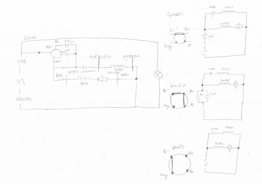
Comparing the above schematics to those derived in the previous post, we can see that the new information has added to what we already knew without contradiction. However, the function of each component is now crystal clear:
- The UNKNOWN capacitor is indeed a starting capacitor, as the inner winding (starter winding) is connected in series to it, with the entire branch (capacitor and winding) connected in parallel to the outer (main) winding.
- The 2.5uF and 3uF capacitors play the role of speed control capacitors, altering the series reactance to both branches and hence reducing the voltage received by both windings. This kind of makes sense, since if the voltage to the main winding was scaled down by a certain factor, the voltage to the stater winding should also be scaled down to the same factor.
Now that I had the full picture of the operation of the fan, there was one more thing left to do: that is to calculate the ideal capacitance value of the UNKNOWN starter capacitor to achieve the perfect 90-degree phase shift between the starter and main winding. In doing so, I would also find out how far off my guess of 3uF for the UNKNOWN capacitance was.
I first measured the resistance and inductance values of each of the windings:
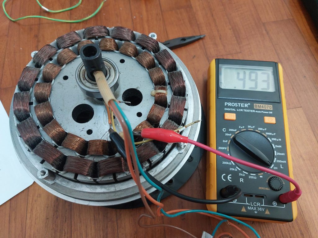
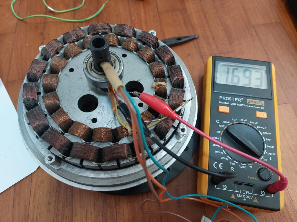
I obtained the following results:
Main Winding: 150Ω, 0.493H
Starter Winding: 200Ω, 1.649H
Calculating the impedance of the main and starter winding using the equation for inductive reactance:

\Omega")
\Omega")
Converting this into polar coordinates:


We will now consider the case where the fan speed is set to Speed 3: there is no capacitor placed between the AC source and both branches.
In this case, the voltage applied to both branches is the same. Hence, we will treat the voltage as the common axis. Since an inductor causes the current to lag the voltage by 90 degrees, the angle of Z_main and Z_starter will be negative (current lags voltage). This yields the following vector diagram:
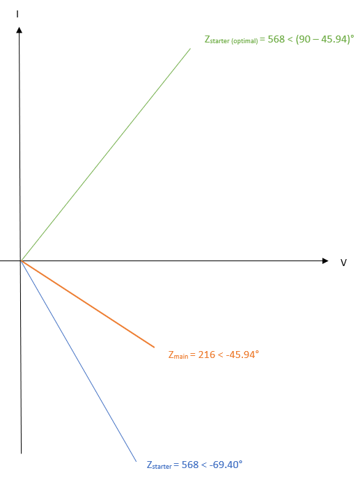
Thus we can see that in order for the current of the starter winding to lead that of the main winding by 90 degrees, the argument of the complex number (angle between V axis and the vector Z_starter_(optimal) must be 90 – 45.95 = 44.06°.
Since we have flipped the signs for the angle due to V being chosen as the reference axis (now inductive reactance results in a negative angle instead of a positive one), we need to flip the signs in our calculation of complex impedance:
\Omega")
Hence, factoring in the effect of the capacitor on Z_starter winding optimal:
j )\Omega")
 = 90^{\circ} - 45.95^{\circ} = 44.06^{\circ}")

 = 716.54\Omega")
Hence since


This meant that my initial guess was off by about 30%. This could explain why the fan did not spin up (or at least spin up to a usable speed) at 1-speed or 2-speed, as the phase difference of the current in the starter and main winding was not perfectly 90 degrees apart. However, this doesn’t really make sense considering that the speed capacitors would shift the current phase at both the main and starter winding to the same extent (since both windings are in parallel), thus it is unclear why the fan was unable to spin up at speeds 1-2 but spun at a faster-than-normal rate at speed-3. Perhaps the mismatched starter capacitor (and by extension, the mismatched phase difference) meant that there was a critical voltage across the main winding for it to start spinning at a usable speed.
Although some questions remained unanswered, it was still a worthwhile endeavour to take apart the fan and derive its working principles.