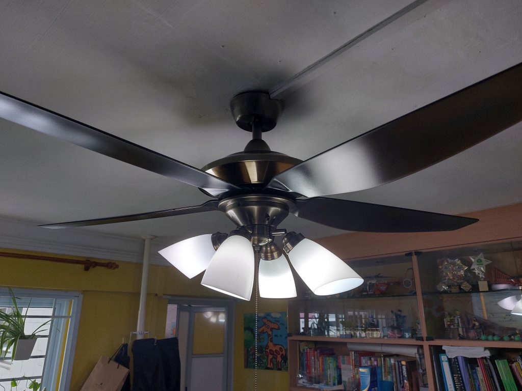
In my bedroom, I have an AC ceiling fan, one that has an integrated light fixture (in my case the lights are in the form of 4 LED bulbs).
However, this fan is notorious for spoiling once every year, requiring us to pay $90 to have it serviced. Having witnessed the technicians come in and repair the fan, I found out that it was always the capacitors that were going bust. Disingenuously, however, the technicians never let me keep the old capacitors, most likely in fear that I would simply order the replacement part myself and repair it, which is exactly what I did this time when the fan broke down yet again.
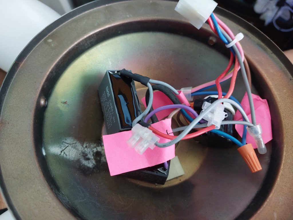
I loosened the three screws holding the fan in place and was greeted with an ugly mess of wires:
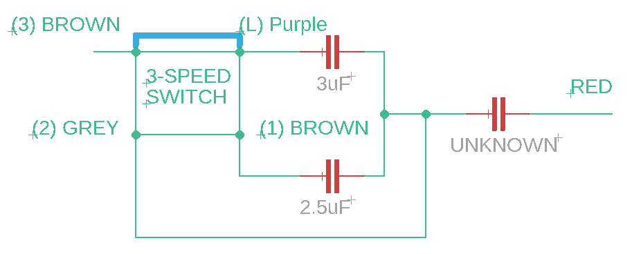
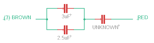
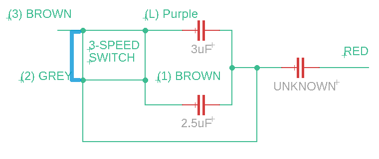
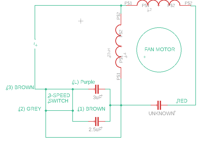
Using my multimeter, I slowly pieced together the connections between all the components. I was left with the following circuit diagram:
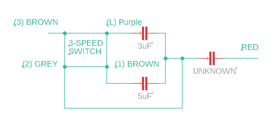
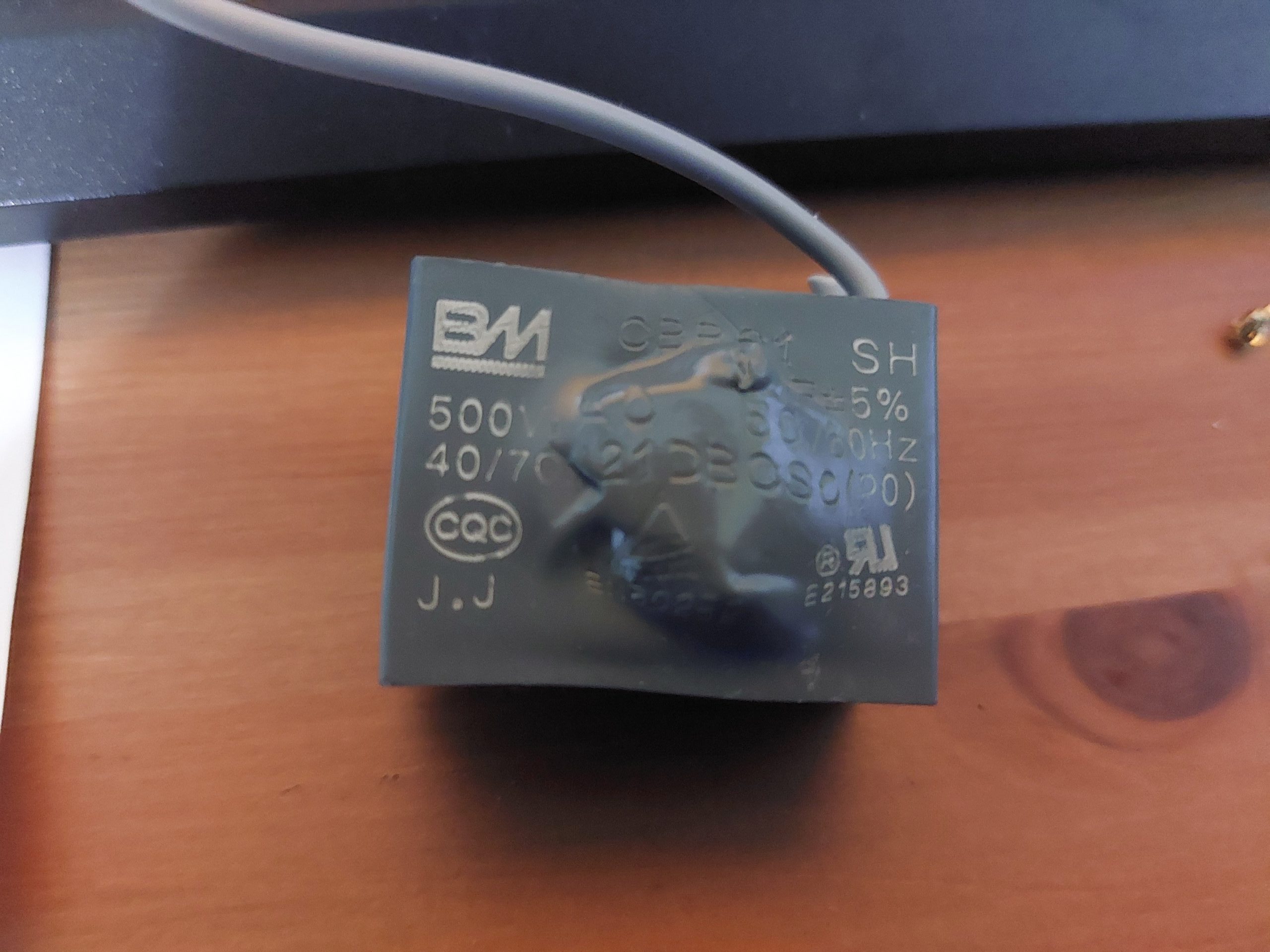
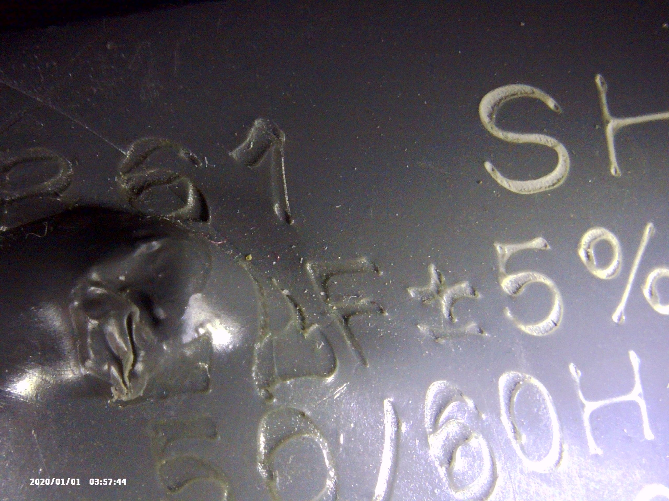
Unfortunately, the value of the third capacitor connected to the (2) GREY wire was not known. This was because the capacitor had bloated, disfiguring the surface with the markings that would have indicated its capacitance value beyond recognition. It was rather sad that of all the other pretty useless markings that could have had been disfigured, the only one that was disfigured beyond recognition had to be the capacitance.
Since I didn’t have the value of capacitance for the last capacitor, I had to do a bit of guesswork in order to find it. The first thing I did was consider the function of each capacitor in terms of how they would aid in the operation of the fan. As this fan was an AC fan, the capacitors could either be used as a starter capacitor, as a speed control (by reducing the voltage to the fan) or perhaps both.
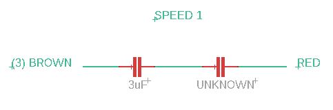
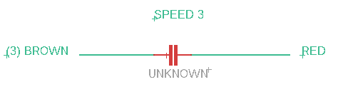
I started by using my multimeter (again) to determine the internal connections of the 3-speed pull-chain switch at the various speed settings (0,1,2 and 3 in order of speed). Referring to the internal circuitry diagram above, the internal connections are as follows:
Speed 1:
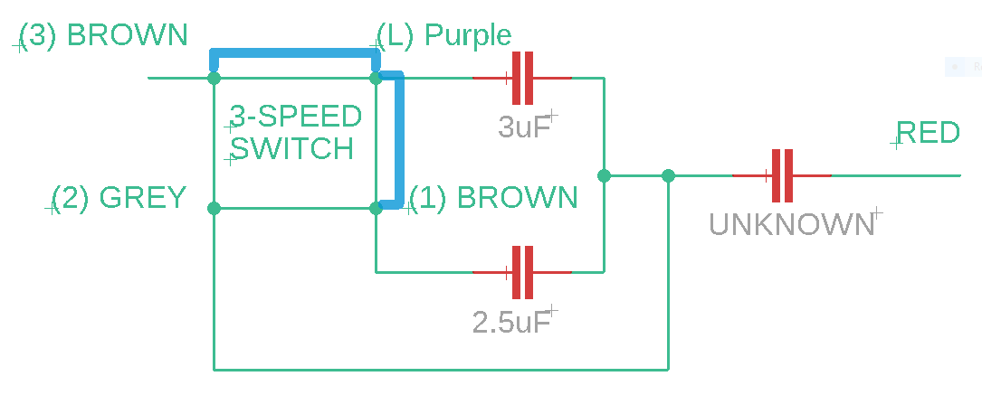
Speed 2:
Speed 3:
At this point, I decided to model the reactance across (3) BROWN and RED to for each speed to determine the appropriate value of UNKNOWN. I did this by plugging in the following equations into Desmos:
Speed 1:
Speed 2:
Speed 3:
^{-1} \cdot 10^{-6}}")
^{-1} \cdot 10^{-6}}")

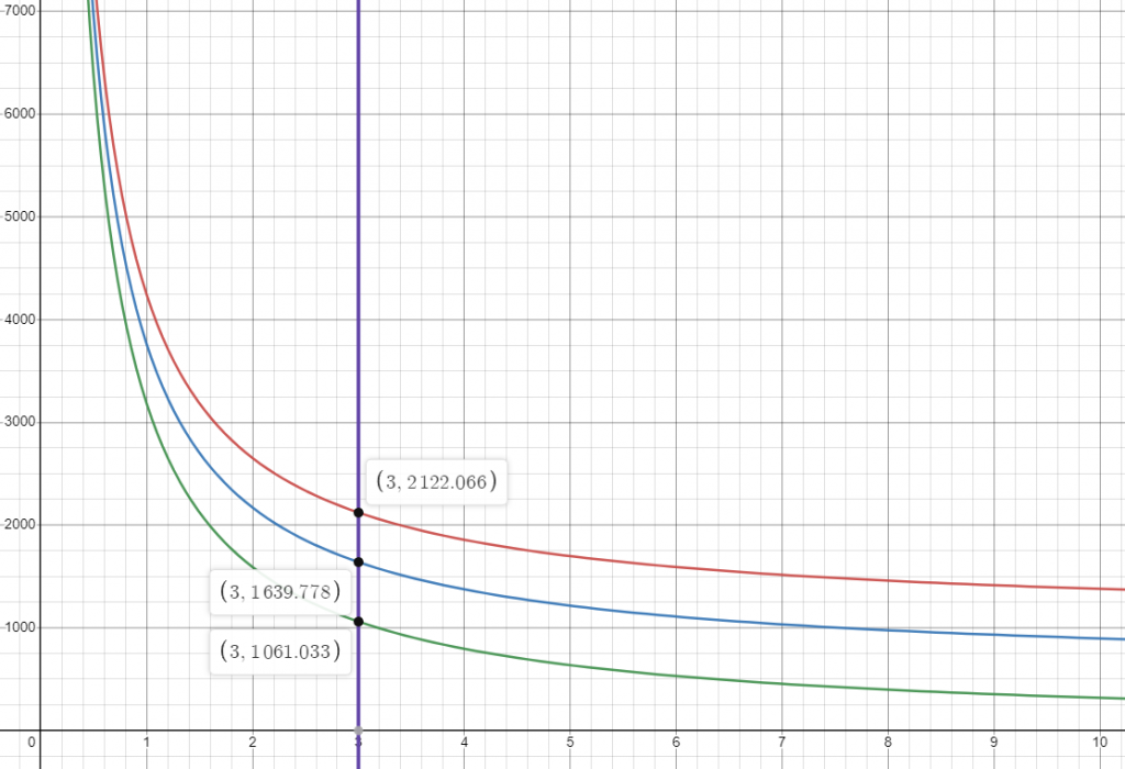
Where x substituted the UNKNOWN capacitor value. Eventually, I was presented with these graphs:
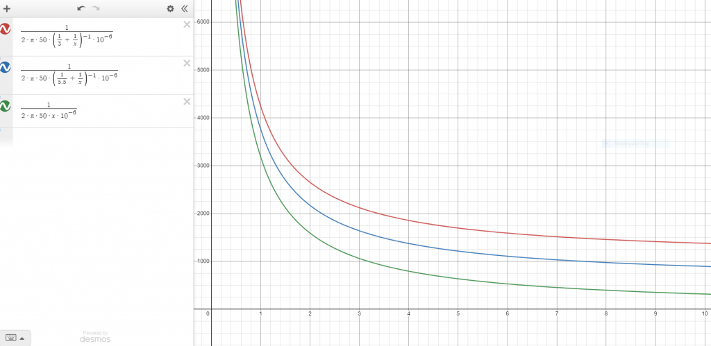
In order to evaluate the most appropriate value of x, I decided to look at the differences in reactances between each graph and select a value of capacitance that would give the evenest distribution. This was based on the assumption that the speed of the fan was solely determined by the value of capacitance between (3) BROWN and RED (via changes in Reactance) and that the fan was designed to have the evenest increments in speed at each setting.
Of course, a major limitation here was that I did not have the full circuit to analyze (there could very well be more components inside the main fan body that could drastically change the equation and graphs). Moreover, I suspected that the UNKNOWN capacitor also played the role of starting capacitor. This was because GREY (2) was connected to the connector that went into the fan’s main body. Thus it was likely that the overall circuit looked something like this:
In any case, I would need to know the resistance and inductance of the coils in order to calculate the required capacitance that would achieve the 90-degree phase split required of a starter capacitor. Then again, I could be completely wrong about the UNKNOWN capacitor being a starter capacitor and it could just be used as a speed control capacitor (I have no way of finding out the internals of the fan unless I rip it from the wall).
Eventually, I settled on a value of 3.0uF for the UNKNOWN capacitor that gave me a pretty consistent reactance interval of 2.1kΩ (1-speed), 1.6kΩ (2-speed), and 2.1kΩ (3-speed). So what was left was to order a 3.0uF capacitor online and test it out.
UPDATE: I installed a 3uF capacitor into the fan and it worked… Unfortunately, it was unbearably slow at 1-speed and 2-speed, only picking up at 3-speed. At 3-speed, it spun slightly faster than usual which was fine by me since I enjoy very strong fan speeds. Unfortunately, the fan simply stopped working somewhere in the night while leaving it on 3-speed. I initially thought that the new capacitor had gone bust but upon opening the fan and inspecting it, it was perfectly ok.
My guess is that the higher-than-normal speed must have caused excessive current heating in the internal coils which led to a burnout of the fan’s coils. Looking back at the graphs, it seems that the intervals between each speed setting were more or less uniform throughout the domain, thus I could have picked any value of x and by this logic, it would have been considered ok. I guess one learning point is to not get complacent/contented with a setting that works well enough, but was doing unseen damage behind the scenes.
In any case, it was a good experience learning about RC circuits and how an AC ceiling fan operates.