Tl;dr: I discuss the consideration and challenges in the hardware aspect of designing motion sensors for home automation.
It has always been a dream of mine to convert my home into a smart home, and a large part of that involves automating the lights in my house. As such, I have been experimenting with various DIY sensors to detect motion, and I am pleased to share the results of my experimentation.
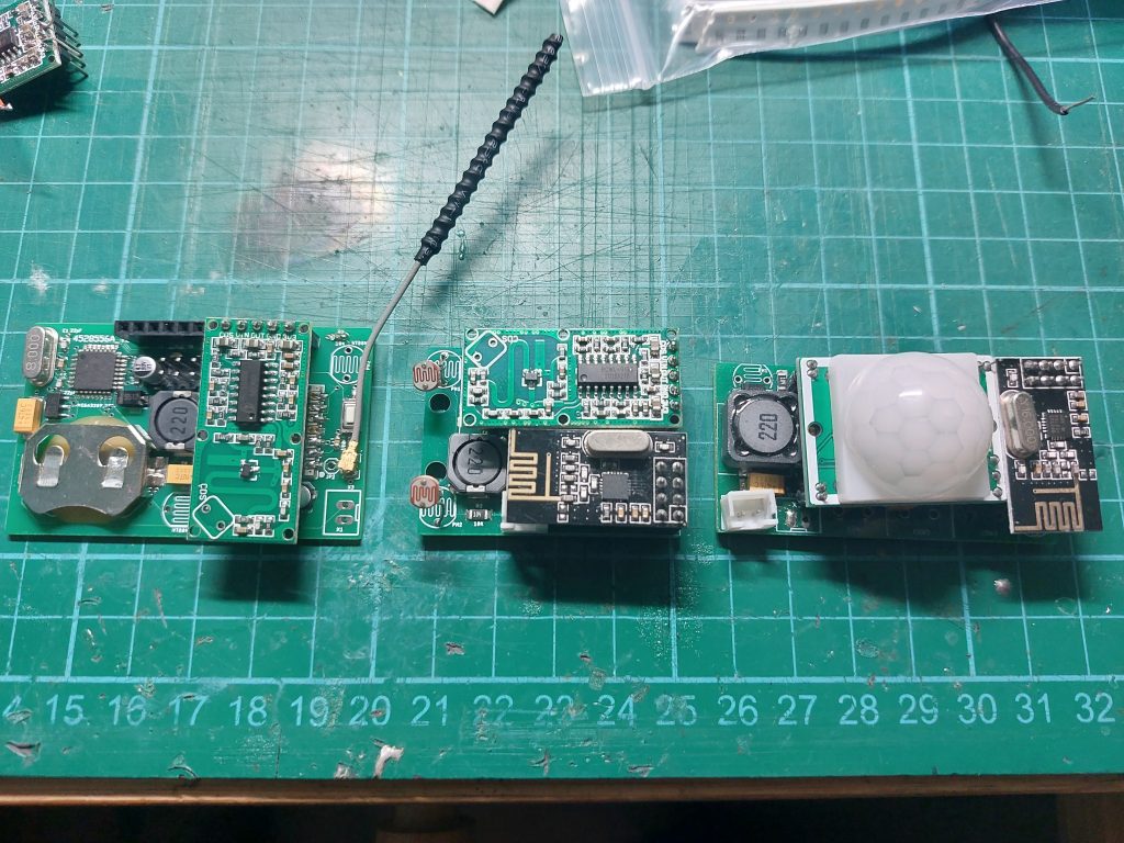
My experiments have revolved primarily around the ATMEGA32(16)8P Microcontroller and the following hardware. For radios, I experimented with the NRF24L01+ and the RFM69 modules and as for the motion sensors, I experimented with the HC-SR501 as well as the RCWL-0516 sensor. As for the smart home controller, I am using Home Assistant OS running on a Raspberry Pi 4 with MySensors as the transport protocol.
Ideally, the motion sensor should possess the following characteristics:
- High sensitivity (or at least enough to detect the motion of a human)
- Low rate of false positives (to prevent unwanted turning on of the light when nobody is around)
- Low power consumption (long battery life to reduce the frequency of battery changes)
- Light Detection capabilities (achieved through adding a Light Dependent Resistor)
As I would soon come to realize, balancing the first and second characteristics proved to be extremely difficult.
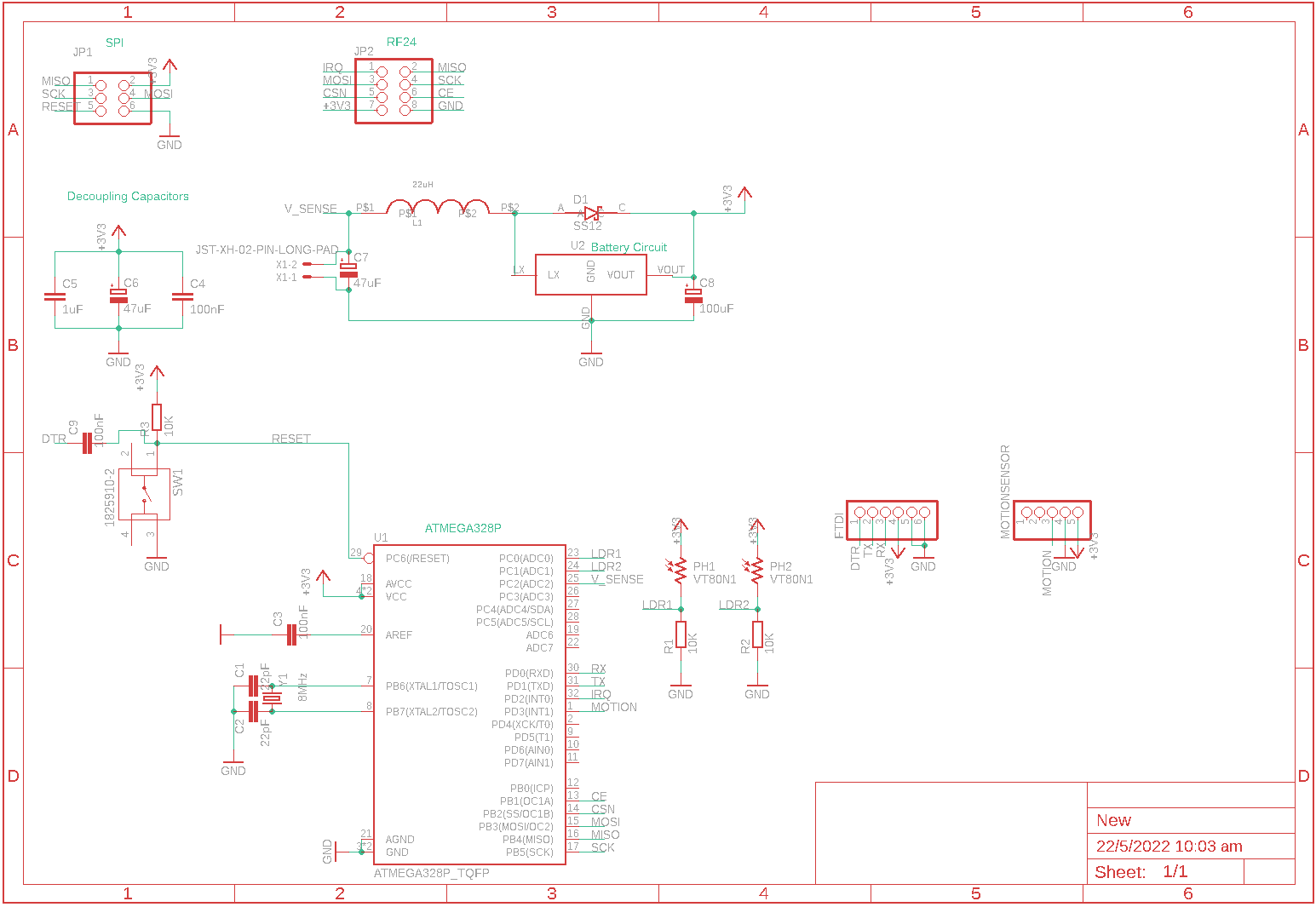
My first attempt at the motion sensor was with the NRF24l01+ radio module and the HC-SR501 Passive Infrared motion sensor. I chose the NRF24L01 as it was available extremely cheaply from a wide range of suppliers on online shopping websites such as AliExpress. Moreover, the NRF24L01+ modules come with an integrated PCB antenna that would reduce the need for an external antenna or for designing a PCB antenna. Similarly, I chose the HC-SR501 motion sensor as it was available cheaply and a staple for many DIY Arduino projects involving motion detection.
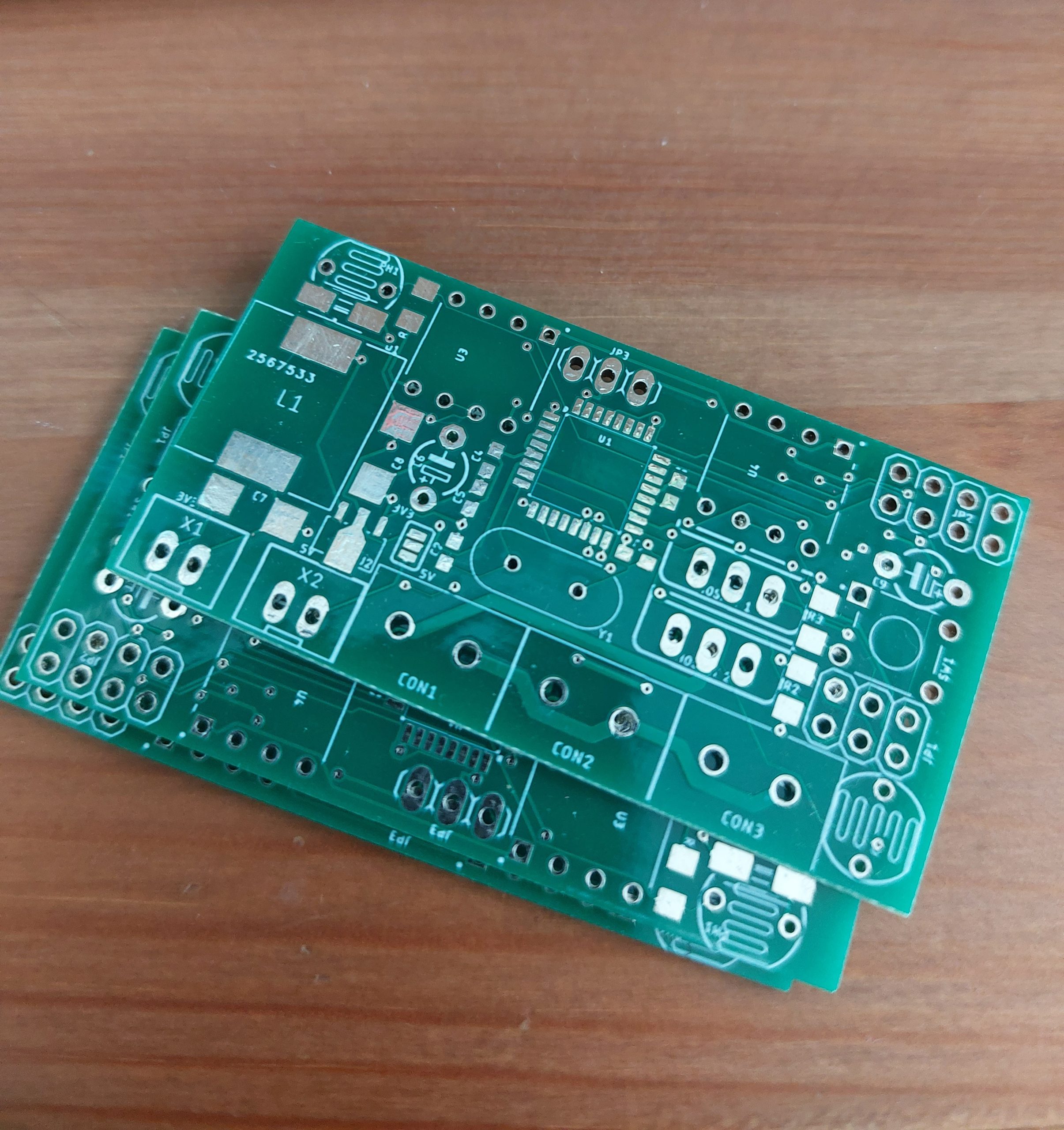
My first board design was rather undeveloped and contained many mistakes that would make troubleshooting an absolute pain in the ass. For starters, I omitted an FTDI adapter pin header to save board space, believing that it would be possible to upload my code solely via ICSP (In-Circuit Chip Programming). Although it was indeed possible to upload the program to the chip via ICSP, the lack of a Serial connection meant debugging via Serial Prints was impossible. This turned out to be a huge problem for me when I started testing the board.
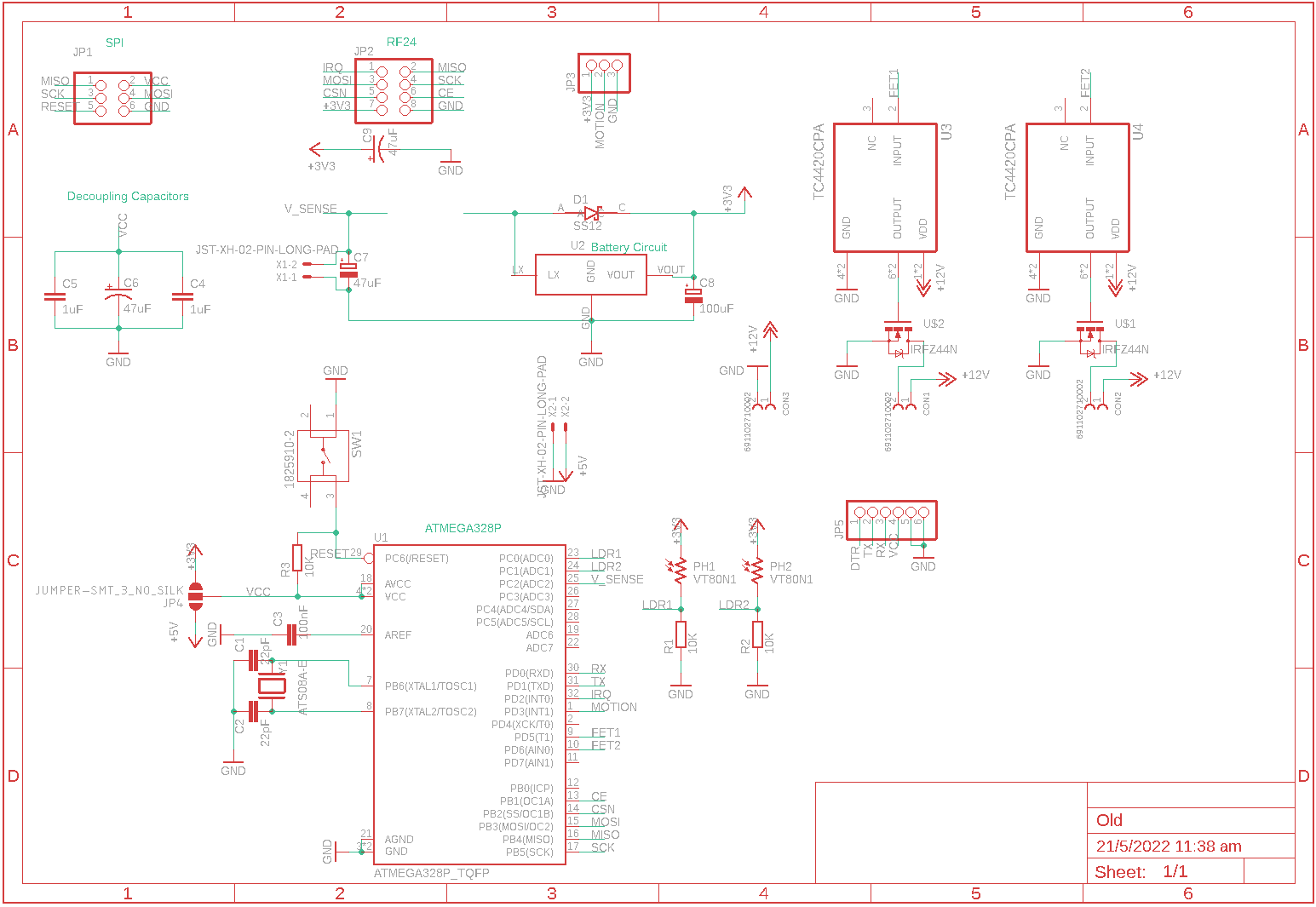
Since the NRF24L01+ was a 3.3V logic device (the IO pins are technically able to withstand 5V), I decided to reduce the complexity of the overall design by having the main MCU operate at 3.3V as well. That way, there would be no need to have a separate 5V rail in addition to the 3.3V rail (the NRF24L01+ only accepts a maximum of 3.3V for power). This would help save on component costs as well as precious board space, not to mention the reduction in power draw which is critical for battery-operated devices (voltage regulators induce power loss due to the voltage dropout).
After soldering the components to the board, the main problem I immediately faced was connection issues with the gateway. Although I was using an upgraded model of the NRF24L01+ on the gateway (with a low noise amplifier to boost the range), the sensors would randomly go offline. This became so bad to the point that devices would simply fail to show up on the gateway logs for hours on end, rendering the system totally unusable.
Another problem faced was the constant false triggering of the sensors when they did connect to the gateway. This resulted in the lights being turned on at random hours of the night, causing the occupants of the room to wake up in order to turn it off (since the delay was set to turn off after 5 minutes of inactivity). This ultimately resulted in the entire system being taken off the grid while I attempted to rectify the problem (which typically just involved me power cycling the board).
At first, I thought that the issue was due to sensitivity issues of the HC-SR501 PIR motion sensor causing no messages to reach the gateway as the sensor was failing to trigger. This theory was supported by the fact that the sensor did often trigger correctly once in a while (often resulting in false positives), thus leading me to think that the issue was with the sensor, not the radio. As mentioned, I had no access to the Serial debug log of the sensor (due to my lack of foresight in not adding an FTDI header) and hence had no way of finding out if the sensor was even connecting to the gateway in the first place (on hindsight I could have written a sketch that sent data to the gateway periodically and check the receipt of the data in the Home Assistant Logs). I then attempted to retrieve the Serial log of the MCU by soldering wires to the TX and RX pin of the ATMEGA328P. However, that went unsurprisingly disastrously as the pins of the ATMEGA328 were too small to solder on wires accurately. The lack of Serial Debugging was a major contributing factor to the design of the second modified board.
After doing research on the HC-SR501, I inadvertently stumbled upon another motion sensor: the RCWL-0516. Touted as a “Doppler Radar“ motion detection sensor, the RCWL-0516 offered the immediate advantage of being much smaller in form factor and the ability to detect objects while enclosed. This was a major boon as the motion sensors were also to be placed in the toilets, meaning that moisture was likely to be a problem. The RCWL-0516 allowed the entire sensor to be enclosed in a casing, reducing the likelihood of moisture entering the sensor and causing water damage to the circuitry.
With this and the lessons learnt from the previous design, I set about designing and fabricating V2 of the motion sensors, this time with a pin header row for an FTDI adapter in addition to the ICSP header. However, I still used the NRF2401+ as the radio module as I presumed the issue to be with the sensor, rather than the radio. My confidence in the NRF24L01+ was also bolstered by a few units that seemed to work perfectly right out of the box. In hindsight, I regret trusting the NRF24L01+ as I soon realized that the quality of these cheap, counterfeit modules varied so wildly that getting them to work was as random as rolling dice.
It was during the testing of the second design (with the aid of the Serial Monitor) that I finally realized that it was the NRF24L01+s that were bottlenecking the entire sensor system. It was then that I realized that the nodes were randomly unable to connect to the gateway (FPAR: !TSM errors) and hence that there were issues with the NRF24L01+s. I subsequently proceeded to change out the NRF24 modules with supposedly “higher-end” modules (those with an IPEX antenna connector for connecting an external antenna) and LNAs. However, it seemed that at 3.3V logic level and 8MHz operating frequency, NRF24L01s simply refused to operate reliably. This was rather strange as all other NRF24 nodes operating on a 5V Arduino nano board seemed to work perfectly fine. Nonetheless, this prompted me to search for a substitute radio for the project.
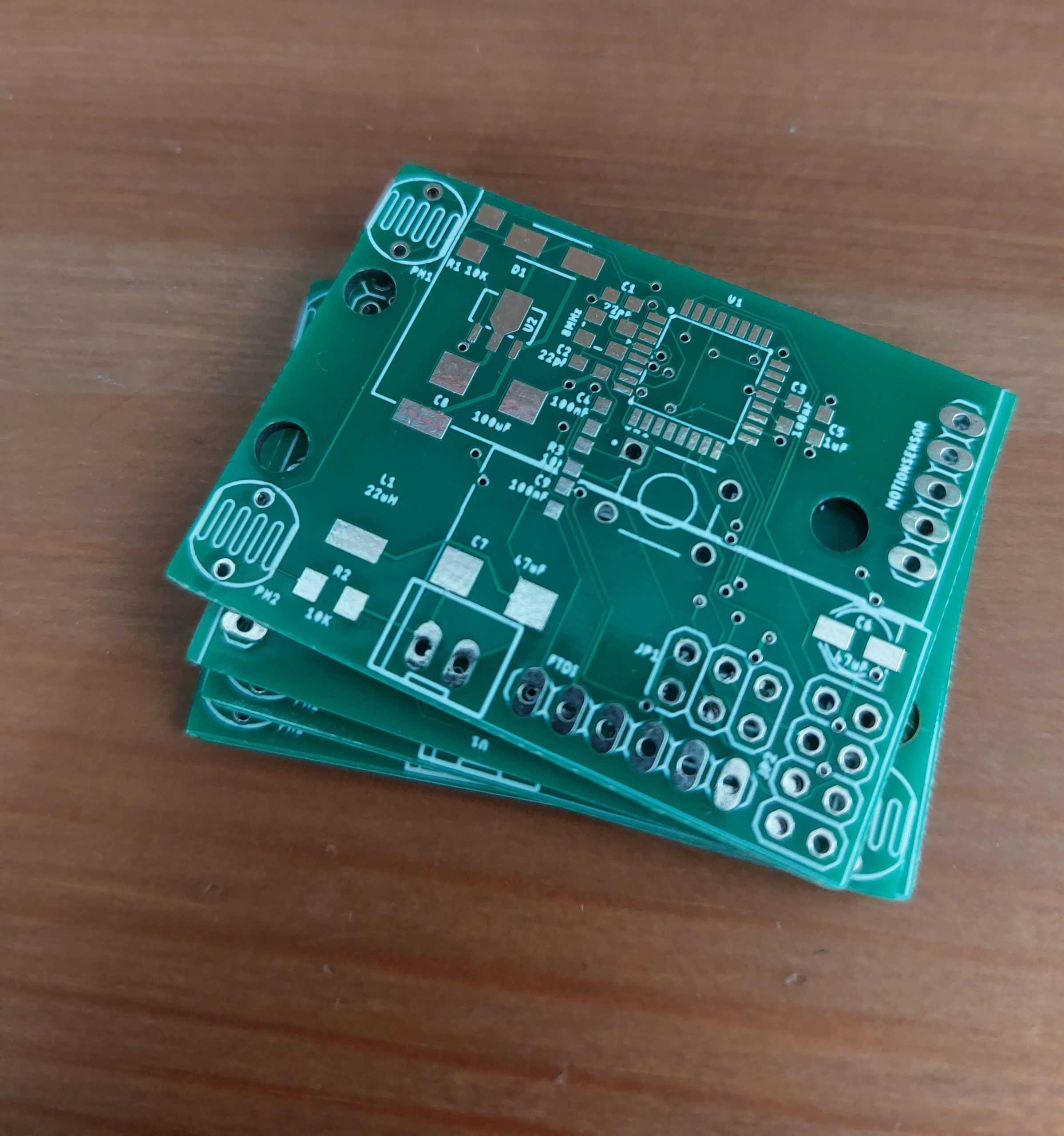
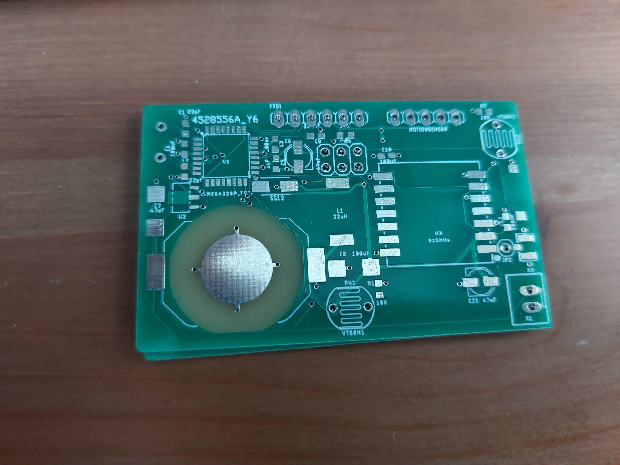
On the MySensors website, the only other supported radio is the RFM69/95 radio, based on the HopeRF module. Although these radios are pricer, they are reported to be more reliable and have a longer range than the NRF24L01+. As such, I redesigned the board once again, giving rise to V3.
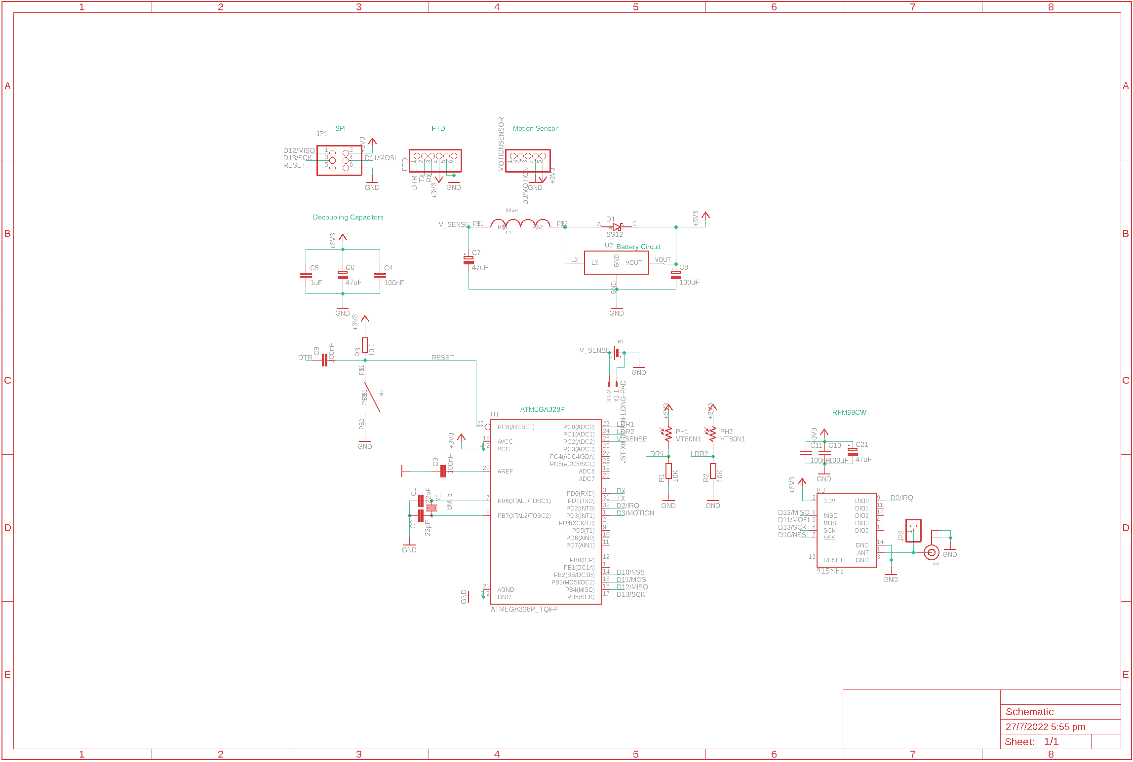
After experimenting with the RCWL-0516, I found that it was extremely sensitive to RF emitted by surrounding devices. I confirmed this by using an oscilloscope to probe the analog input pin of the RCWL-0516 board and discovering that when the neighboring RFM69 initiated a transmission, the signal on this line would oscillate wildly, being immediately interpreted as motion and causing the board to output high on the OUT line. This would have led to many false positives in actual implementation.
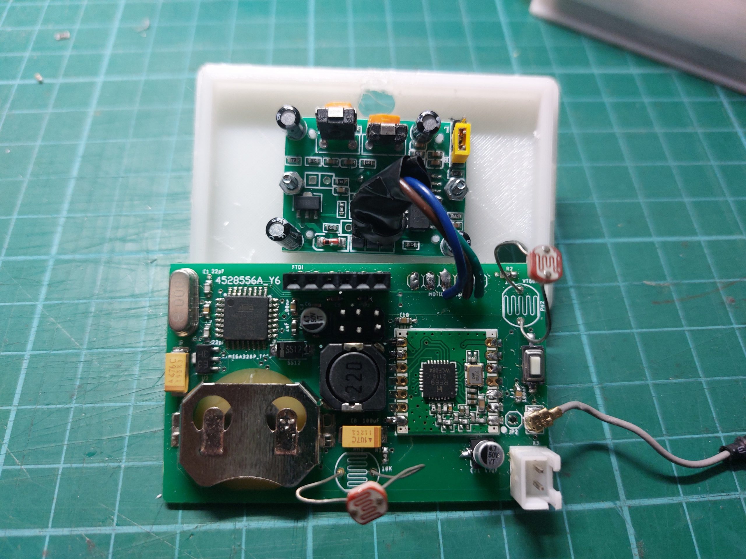
Unfortunately, I had already fabricated the PCBs to accommodate the RCWL-0516 radar sensor. Nonetheless, I decided to revert back to using the HC-SR501 PIR sensor. This was done by manually soldering wires from the pin headers on the PCB to the respective pin headers on the HC-SR501 PIR sensor (this was necessary because the pinout on the RCWL-0516 sensor is different from the HC-SR501). Since there are only 3 connections (VCC, OUT and GND), this was well worth the effort instead of wasting money refabricating a new PCB and throwing the existing ones away.
As such, I was left with a rather neat final product:
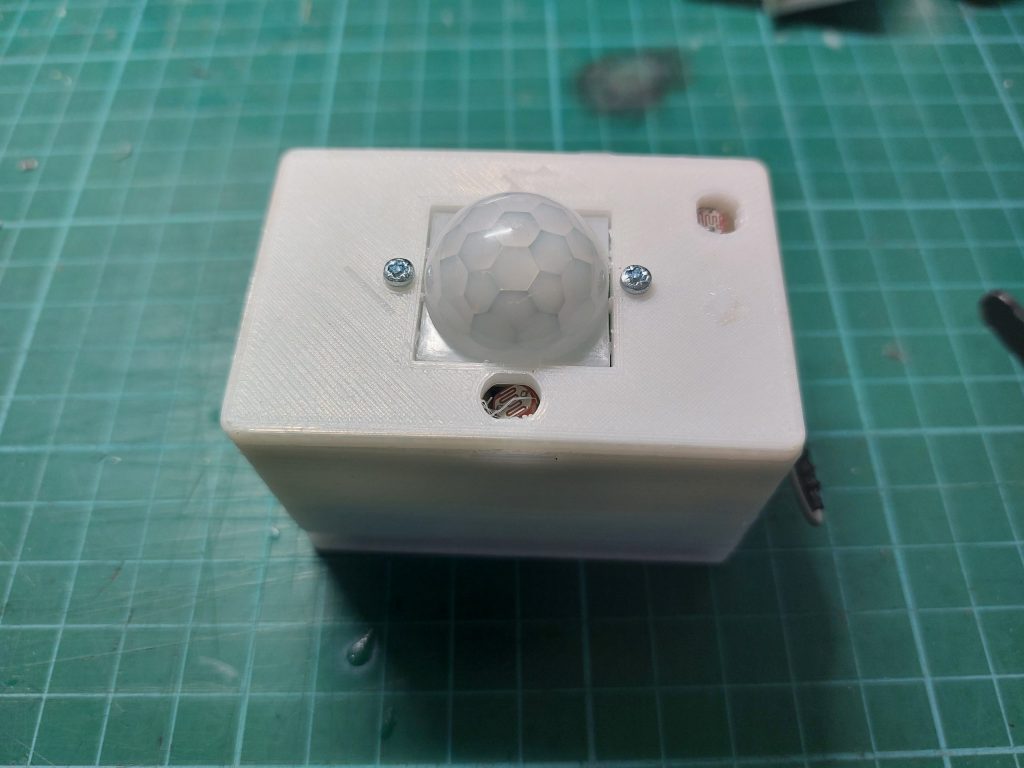
The entire circuitry is housed within a 3D-printed case, with the PIR sensor and the LDRs protruding out at the top. The top case is detachable, revealing the internals.
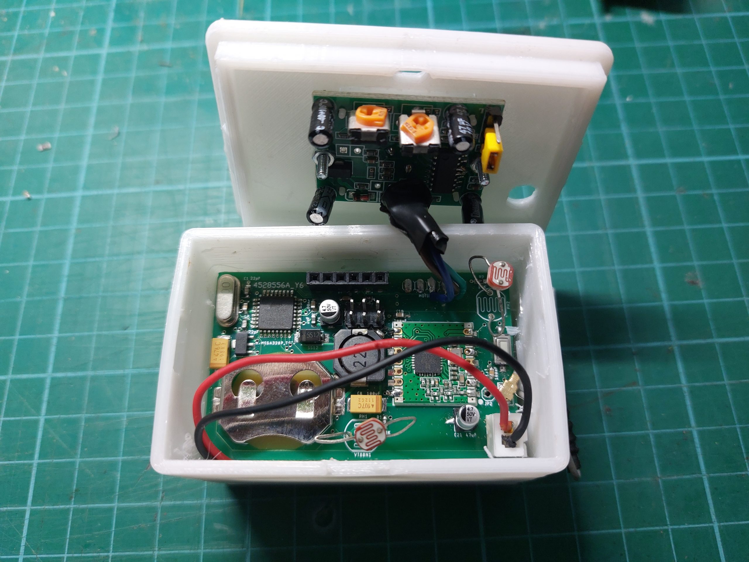
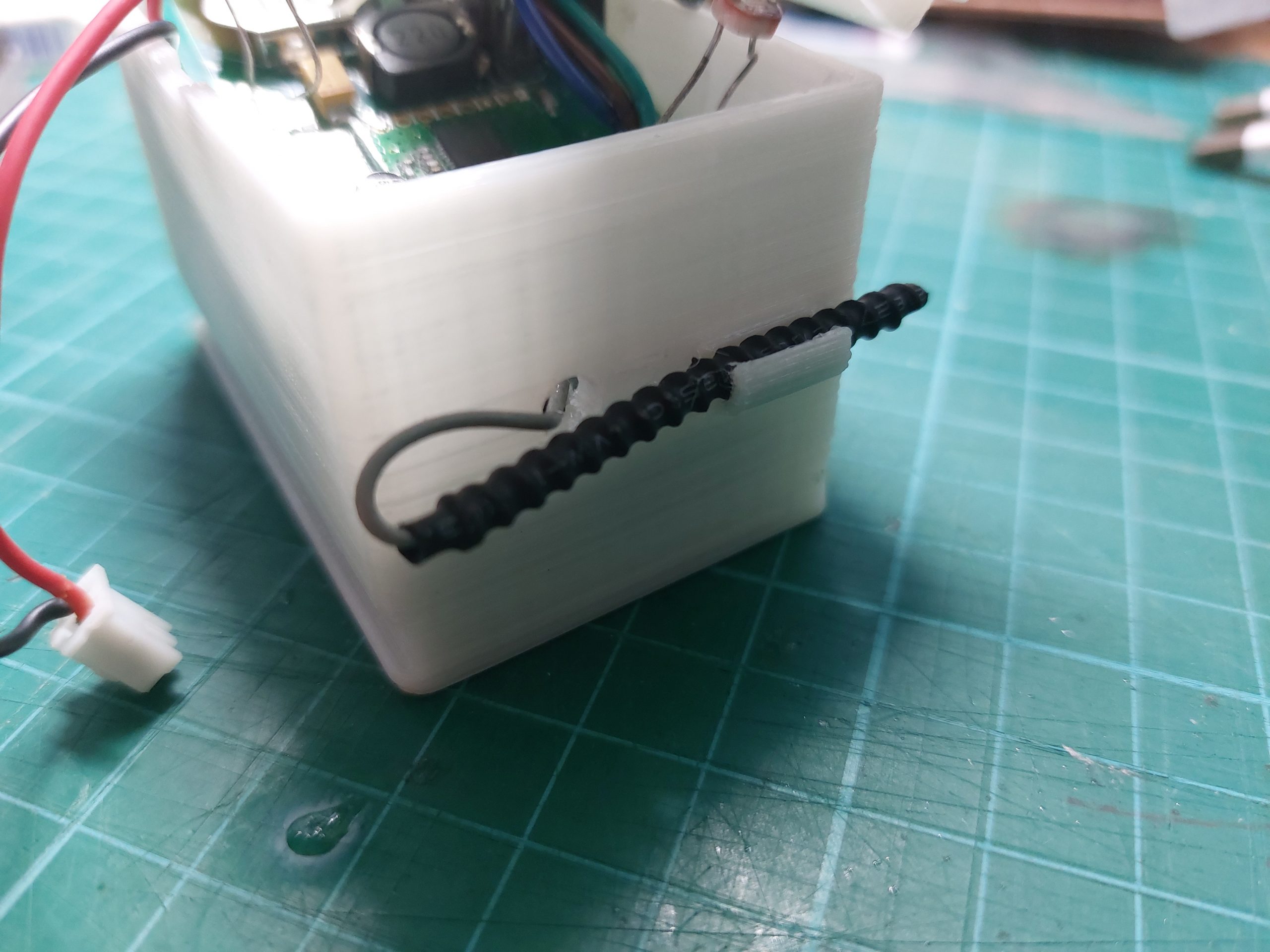
As for the antenna, I decided to go with an IPX aerial antenna due to its small form-factor but decent SWR characteristics as well as the fact that it could be mounted outside of the case, away from the electronics (unlike the coil antenna that typically is used with the RFM69 module).
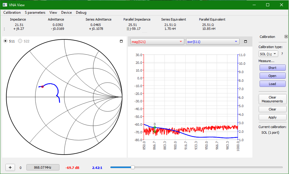
The antenna is mounted to the side of the case by a clipping attachment. So far this setup has worked great with no noticeable loss in transmission.
Overall, I am quite happy with this final design of motion sensors. It looks sleek, does the job, and doesn’t cost much. Overall, the costs can be broken down as follows:
- PCB board: SGD$1.20
- RFM69 Radio Module: SGD$2.40
- IPX Aerial Antenna (868MHz): SGD$1.30
- HC-SR501: SGD$1.20
- ATMEGA168P (once the prototyping was over I could disable SERIAL_DEBUG and use the ATMEGA168P with less flash but costs less): SGD$1.40
- SMD Components: ~SGD$2.00
- 3D Printed parts: <100g ~SGD$1.50
Total Cost: ~SGD$11 which is really not bad at all.
However, some noticeable drawbacks of this design have been noted over the course of use:
- The HC-SR501 can be set in 2 modes: repeating trigger (which will reset the timeout timer and keep output high if motion is detected before the timeout ends) and single trigger (which will keep output high for a set period for time and then drop it back to low even if motion is detected again during the timeout period). I found that the repeating trigger isn’t always triggered by motion, leading to cases where the light automatically tuns off (as programmed in Home Assistant) despite there being a person still in the toilet. Typically this occurs when a person is using the toilet to shower. As you can imagine, it is not the most pleasant of experiences to be plunged into darkness while showering.
- The battery life of these sensors is rather short at around 2-3 months (of course depending on the location these sensors are deployed and the corresponding footfall at these locations). I have yet to comprehensively test the current consumption of these devices (as I lack a precise lab bench power supply) but will do so when it becomes available.
All in all, I am extremely satisfied with this project, knowing that it will greatly improve the convenience of occupants in my household (aka my family), given that they now no longer need to manually switch on and off lights (perhaps this inculcates bad habits but I guess this is the whole point of technology), as well as reduce electricity costs from lights left on when nobody is using them.
Future improvements are likely to come in the form of a more robust way to determine if a person has indeed entered the toilet. One idea floating at the top of my mind is to use Time of Flight (ToF) sensors to track the number of people entering and exiting from a room. By interlacing a system of such sensors at each possible entrance/exit point, it would be possible to accurately actuate lights and fans (and maybe other devices) based on the number of people in rooms. I will work on these ideas and post them once they are ready.