As part of a proof of concept, I embarked on a project to create solar-powered power banks. The idea originated from a visit to a fellow Maker by the name of Darius three years back at a local makerspace. There he conducted a workshop where he constructed a 3D printed power bank out of a 18650 lithium-ion cell and 3D printed parts. I thought it was cool to build your own consumer electronics but I felt it would be even cooler if the power banks could be solar powered as well.
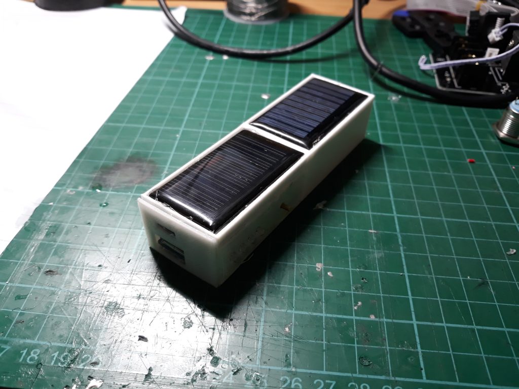
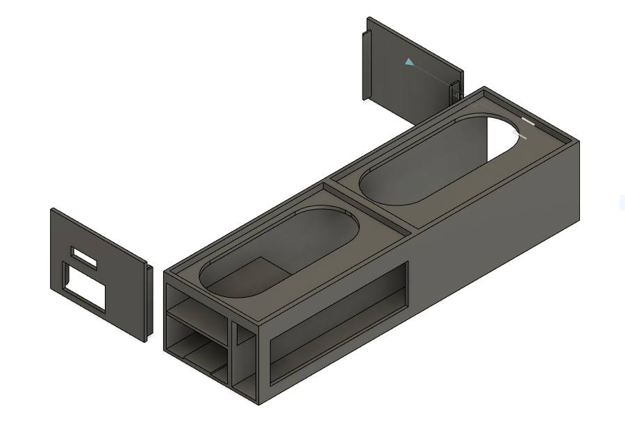
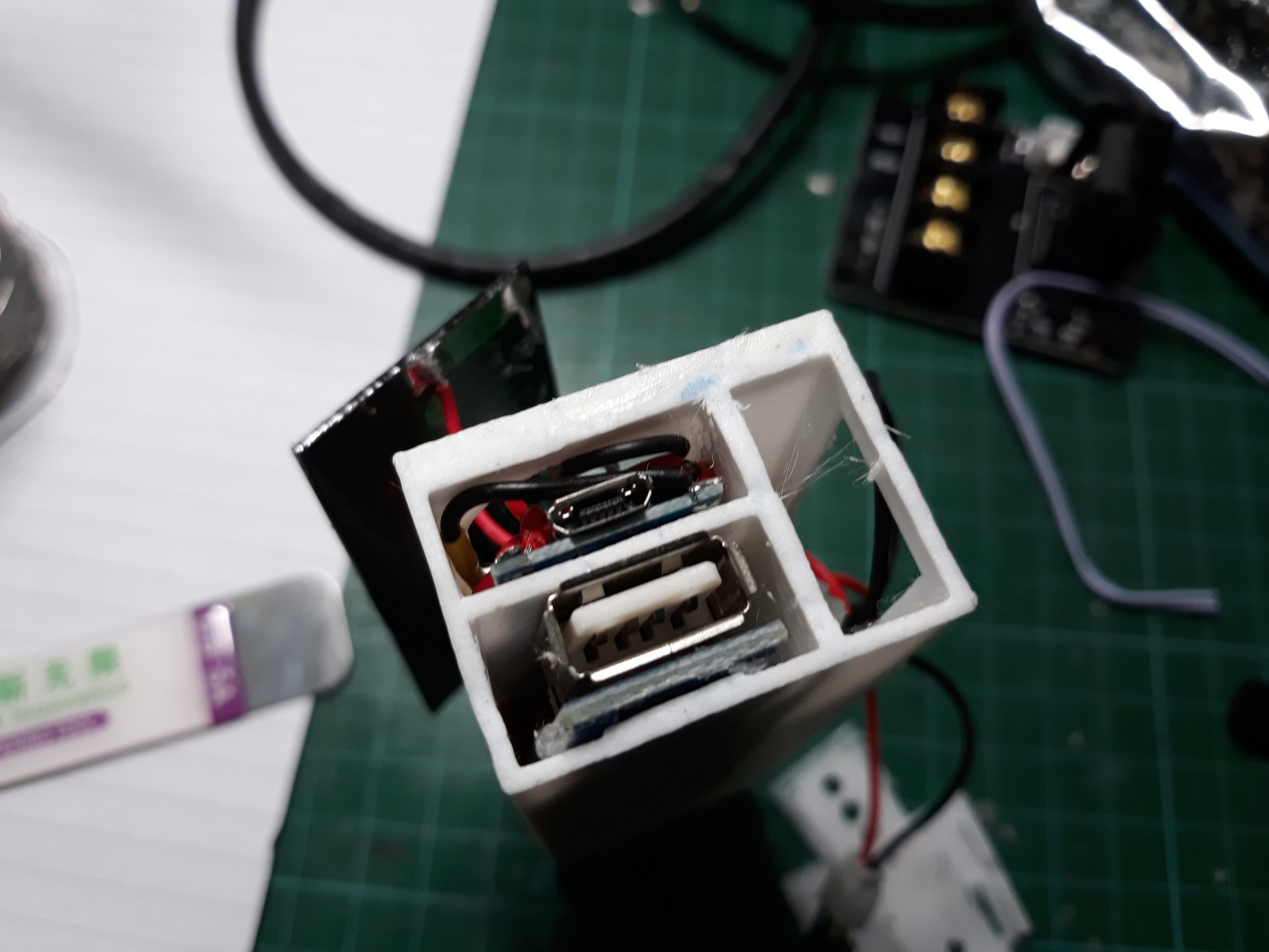
Design wise the 3D printed case was rather simple to pull off – with the basic shape of the power bank being a rectangular cuboid (just large enough to house the 18650 cells and holder). However since the width of the solar panels was a lot larger than the width of the 18650 holders, I extended the overall width of the power bank to accommodate the panels. I then created internal sections to mount the electronics components.
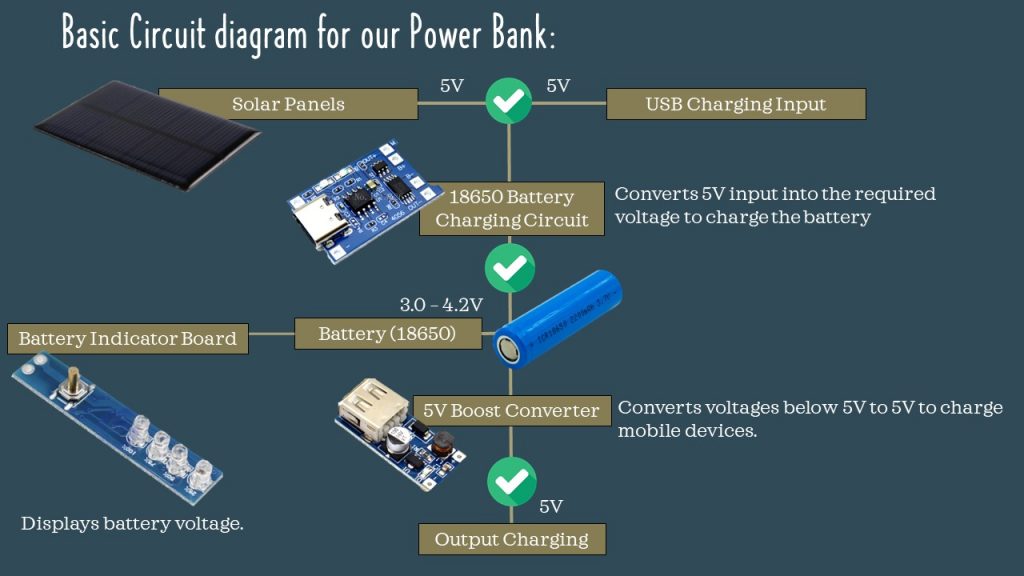
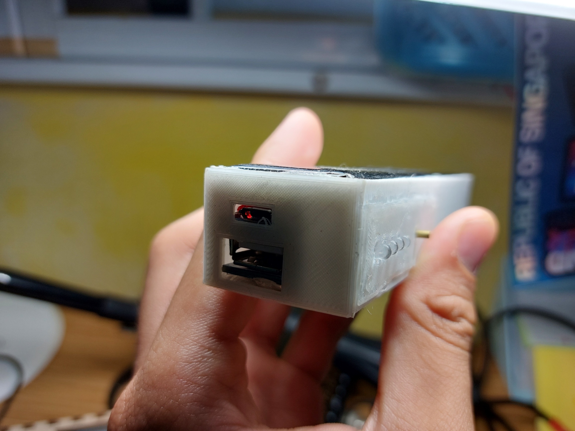
For the power bank, I used the following components:
- 2 x 0.15W solar panels (53mm by 30mm)
- 1 x 5V buck converter
- 1 x TP4056 18650 li-ion charging breakout module
- 1 x USB 5V boost converter
- 1 x batter indicator panel breakout
The basic schematic for wiring the components is as follows:
I then soldered these connections together using 22AWG wires (to be honest even thinner wires worked ok as well) and mounted these components to the sections in the power bank using hot glue. This was by far the most crucial step as the modules would need to be positioned just right so that the USB connectors could be accessed through the corresponding openings. This was achieved in a relatively straightforward manner by using the USB cables to hold the case covers and the electronics modules in place (after sticking the USB cables in) and then applying hot glue and snapping the covers in place, thereby positioning the modules exactly where they needed to be in order to be accessed through the cover panels.
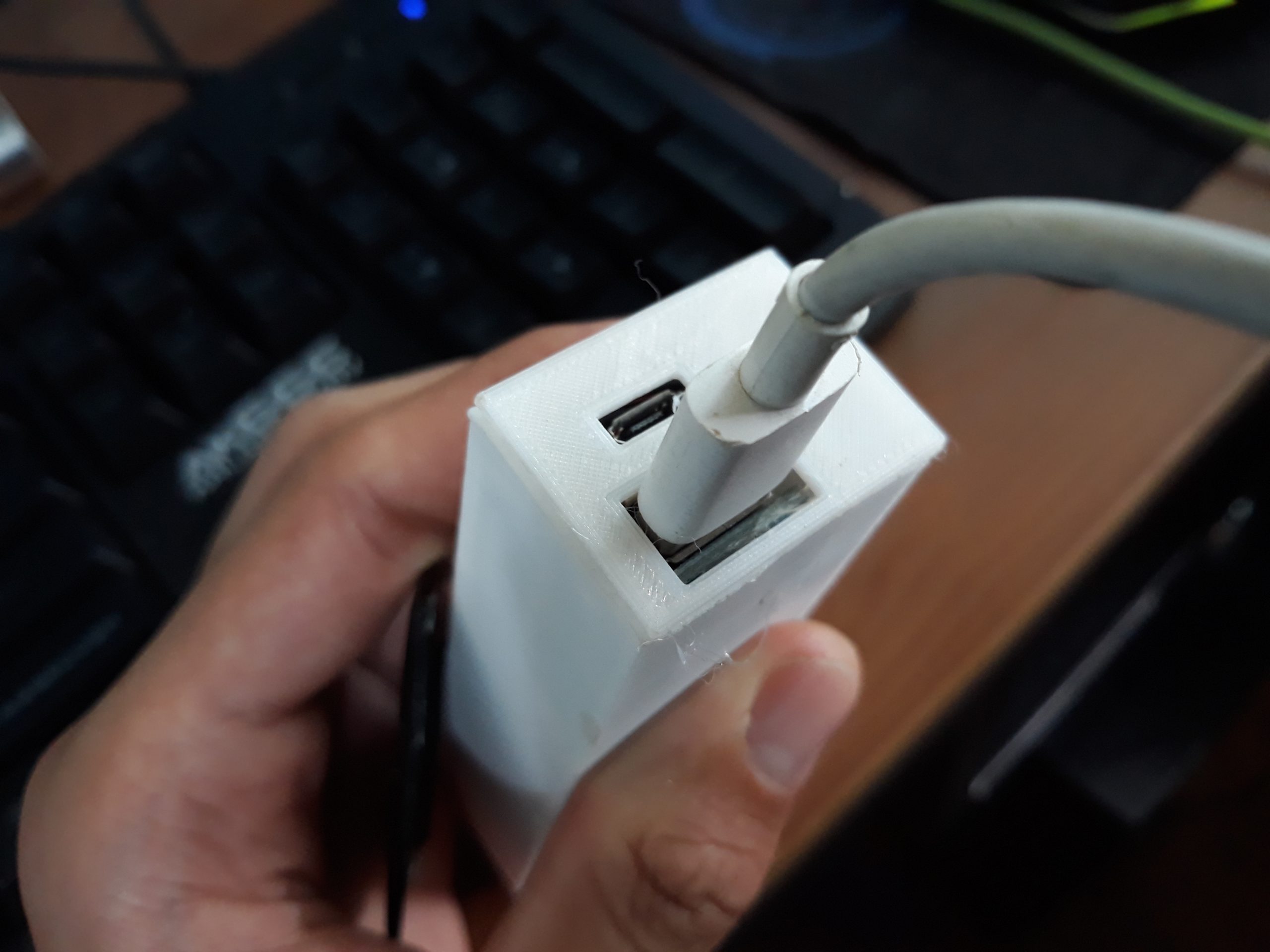
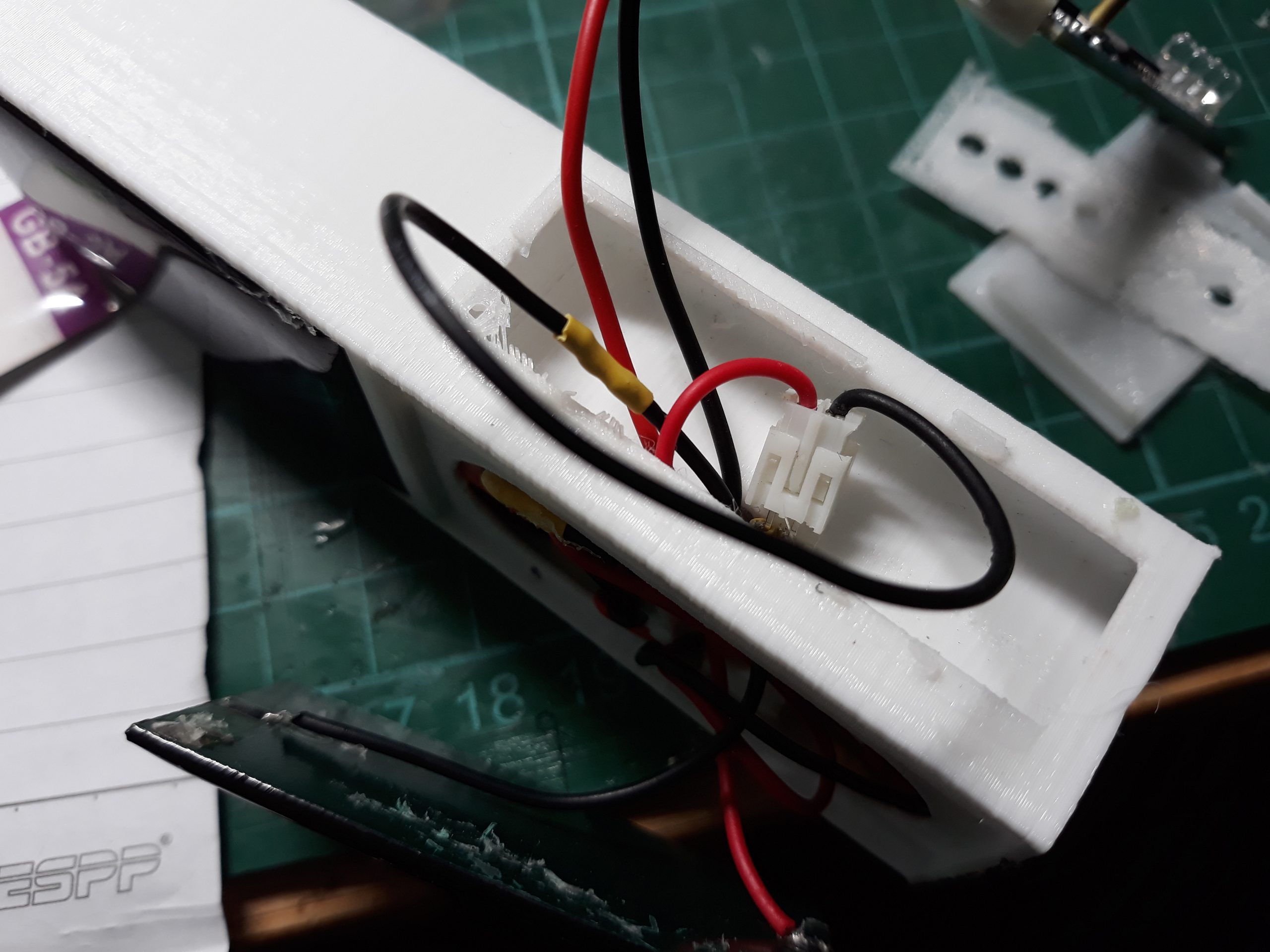
Depending on the economy of wire usage in the previous soldering step, the main challenge for me came with the wiring and associated cable management. As there were many wires connecting the various components, it soon became a real pain squeezing everything into the case. Wire management was a true thorn in the side. This was because if the wires were not packed and squeezed into the case efficiently, the solar panels would not sit flush with the case and thus eventually pop out after some time despite being glued down with hot glue. The unlevel solar panels also made the power banks look really unsightly. This was especially so for a particular batch of solar power banks where I soldered on JST connectors for a school workshop. This was so that the participants would not need to solder and could simply plug the connectors in to make the connections as soldering was deemed to be a significant safety hazard.
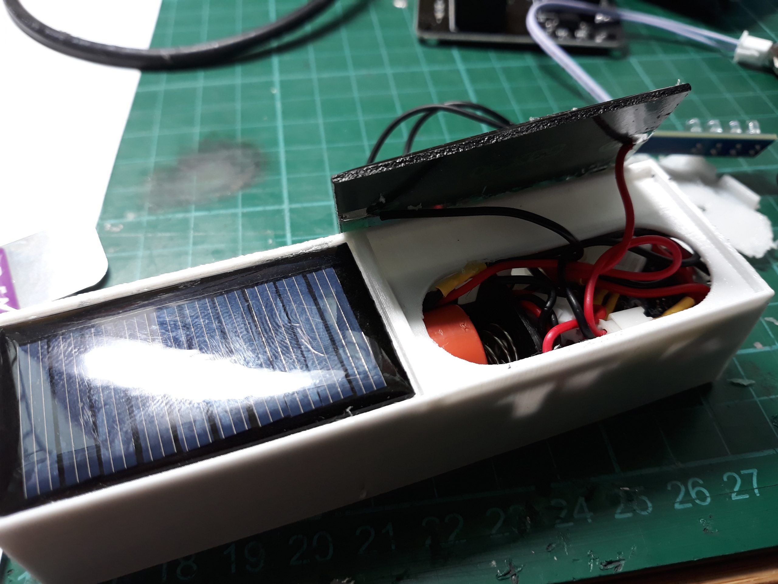
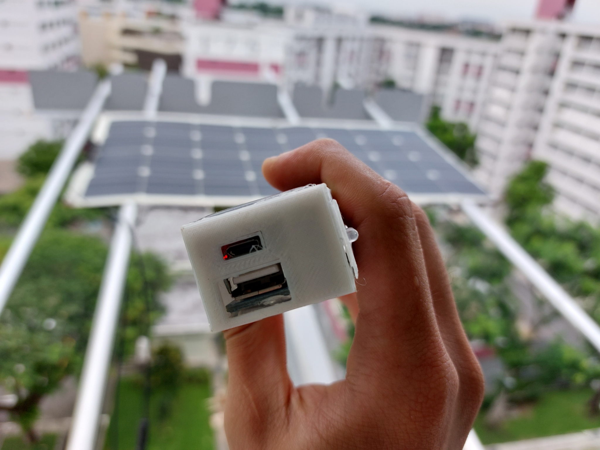
As for the solar aspect, powering the power bank using solar energy was achieved through two 5V 0.15W solar panels mounted on the top of the power bank. Although the actual power output of the solar panels is pretty much insignificant (from my calculations it would take approximately over 30 hours to charge the power bank fully purely using solar power). However, I still felt that this project was worthwhile as a proof of concept. Both panels were wired in parallel so as to maintain the 5V. However as the solar panel was never exposed to the maximum intensity of light required to achieve the theoretical 5V voltage, a challenge I faced was ensuring that the power bank would still charge when exposed to indirect or low levels of light (also I found out that artificial light was a lot worse at emulating real sunlight, as placing the panels directly below a table lamp produced much lower voltage than under indirect natural sunlight).
The first solution I considered was adding more cells in series. However, this was not ideal as the DW01 board has an overcharge cutoff at 4.25V and the TP4056 18650 charging board has a maximum input voltage of 8V. Hence two panels in series would likely produce a voltage of around 8-10V which would be too high.
However placing the panels in series also presents problems to the charging, especially at low light levels. This is because the voltage of the panels is usually around 2-4V at ambient indoor lighting conditions, and hence is often insufficient to charge the power bank. To tackle this issue, I initially tried adding an MT3608 boost converter before the solar panels to boost the panel voltage to 5V. However, I soon found that this was pretty much useless as the voltage remained the same. This was likely due to the boost converter causing the panels to no longer operate at the maximum power point. However, I will need to do a bit more research as I am still pretty unsure about the specifics of MPPT and Impedance matching.
As such the final decision was to leave the solar panels as they were – connected in parallel to the battery charging circuit.
Overall this has been a simple project to demonstrate the proof of concept of a solar-powered power bank. It provided me with a lot of fun designing and soldering and was a good mini-project.