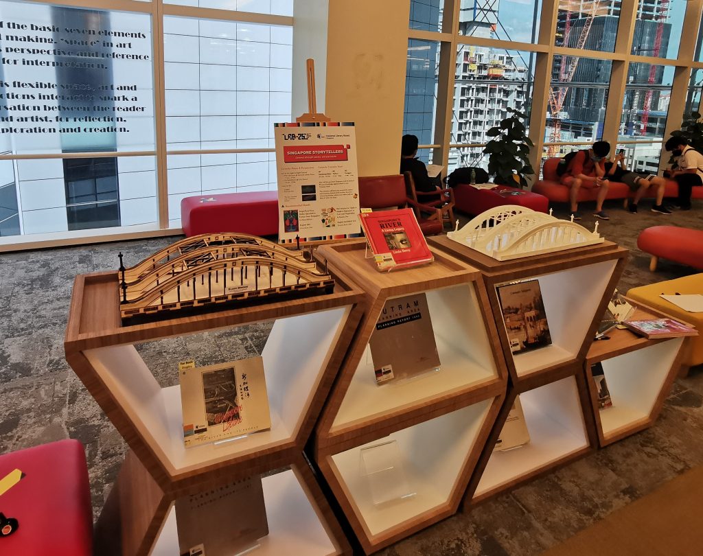
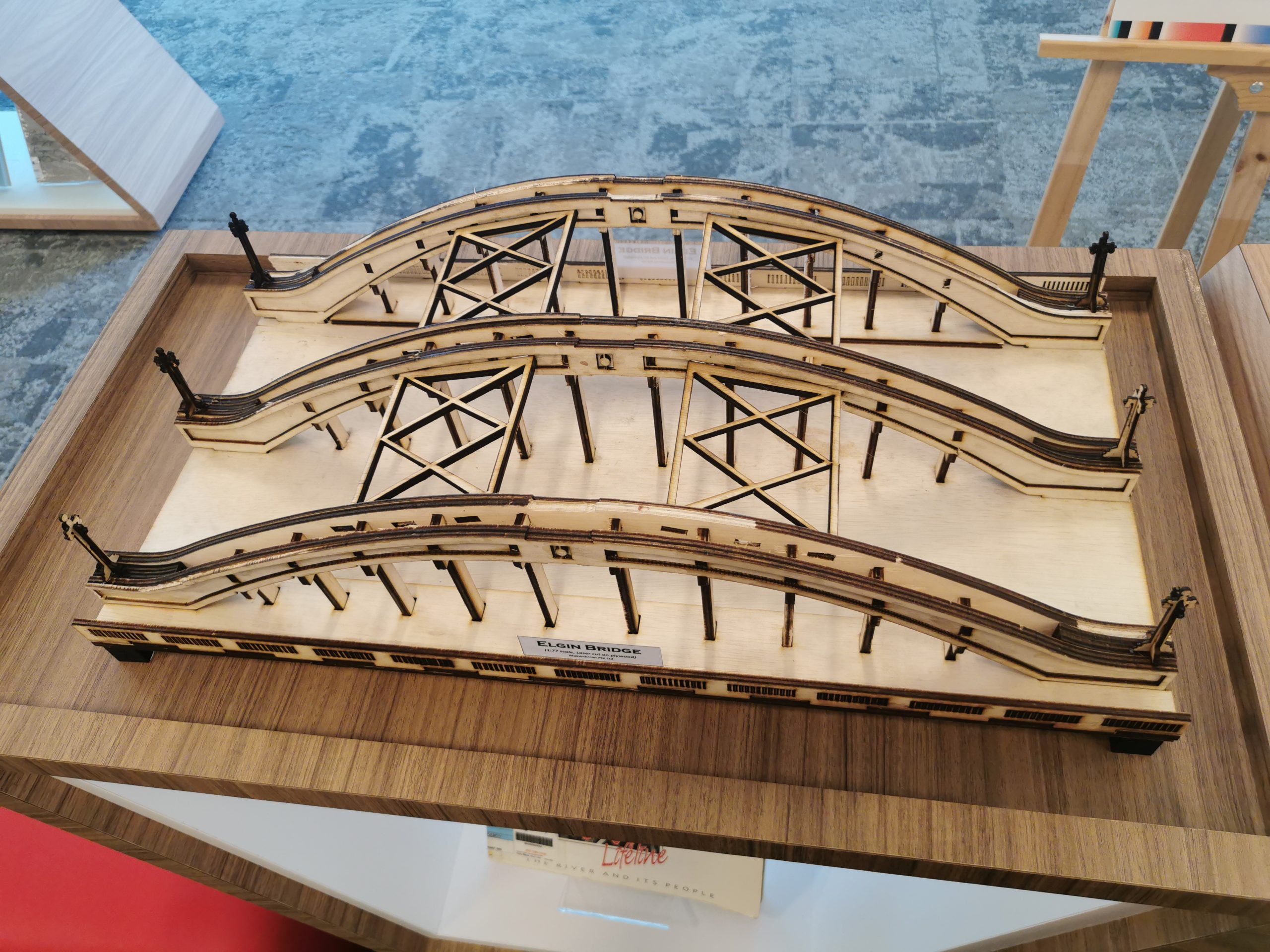
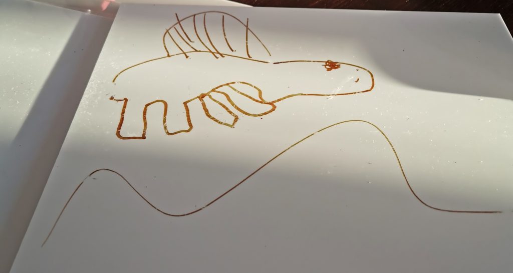
In January 2022, I was commissioned by a friend to design and laser cut scale models of the Elgin Bridge for an exhibition by the National Library Board. As this was the first “full-sized” project involving the laser cutter, I did not know what to expect and to be honest, was apprehensive at the prospect of the laser cutter failing halfway through the project (check out a YouTube playlist on the design, construction and build of the Laser-Cutter here).
Nonetheless, I thought this would be a good opportunity to put the machine through its paces, and as such, I agreed. The deal was that I would create 2 Large Bridges (~65cm long) and 2 Medium Bridges (~25cm long), one in plywood and one in white acrylic. The purpose of the exhibition was to display the various maker technologies and as such the bridges were to be constructed out of different materials.
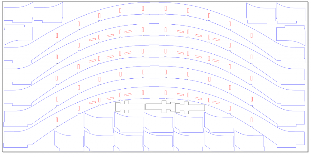
Designing the bridge was relatively straightforward, though I had to revise the designs twice due to changes in the overall size (the Large Bridge was initially designed to be ~70cm). However, the real challenge was to come in the cutting.
Mirror alignment has always been a very elusive aspect of owning, using, and maintaining a laser cutter. This was especially true for a machine of my size since any small deviations in the alignment would have a large effect on the overall error. As such aligning the mirrors before I commenced fabricating the bridges was something I made sure to get right (which was serendipitously how I came to acquire sufficient footage for my YouTube video on mirror alignment).
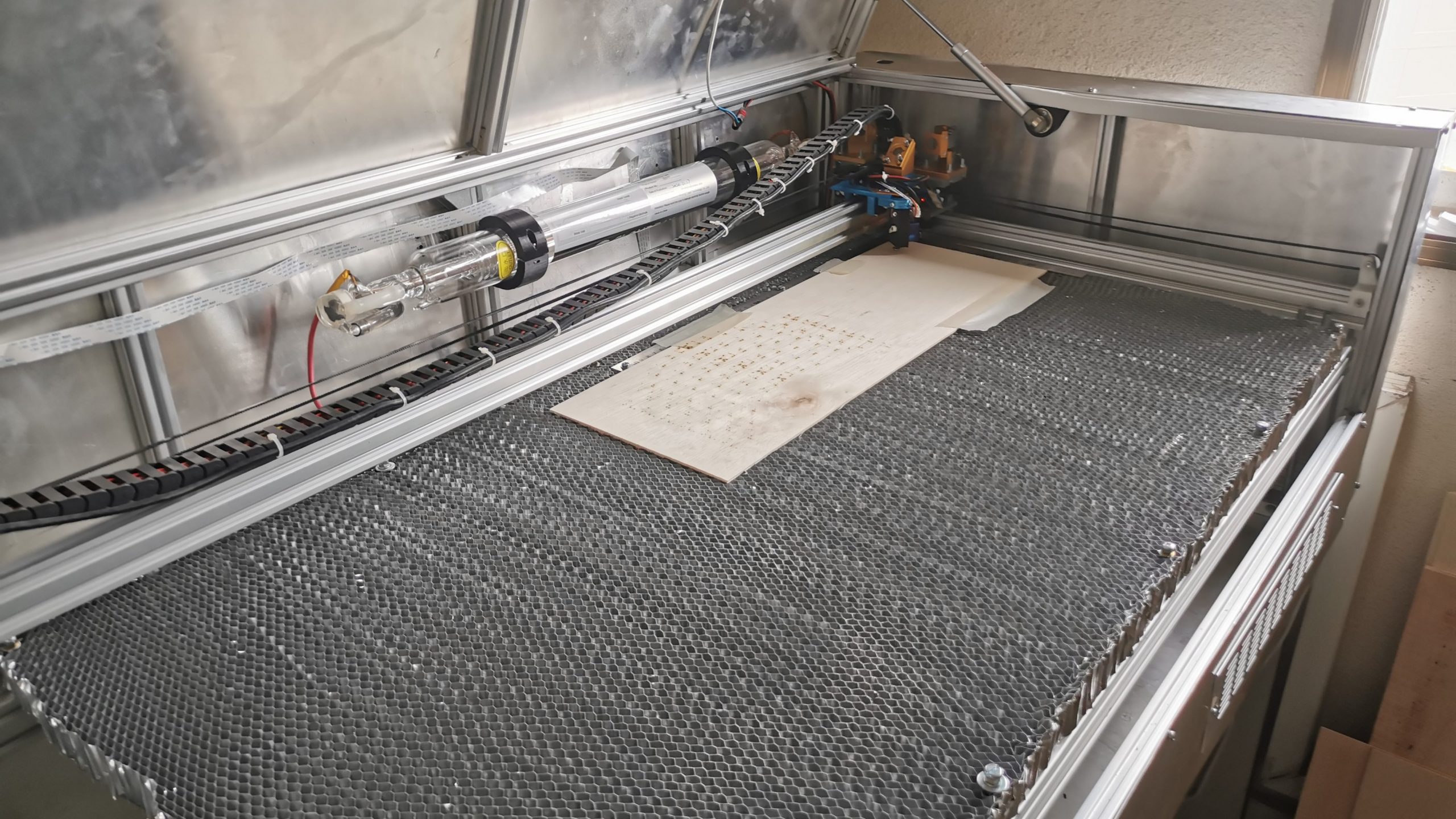
Needless to say, determining the cut rates for my laser cutter on various materials was also a very important aspect of this project. Although I had previously conducted tests on Rastering for 2mm acrylic, I had not tried cutting materials thicker than 5mm (both plywood and acrylic) and as such was even unsure if the 40W laser was sufficiently powerful to cut through these materials in a reasonable amount of time.
Fortunately, testing with 5mm sheets of plywood and acrylic found that the machine was in able to cut through 5mm material at a pretty decent feed rate of 300mm/min.
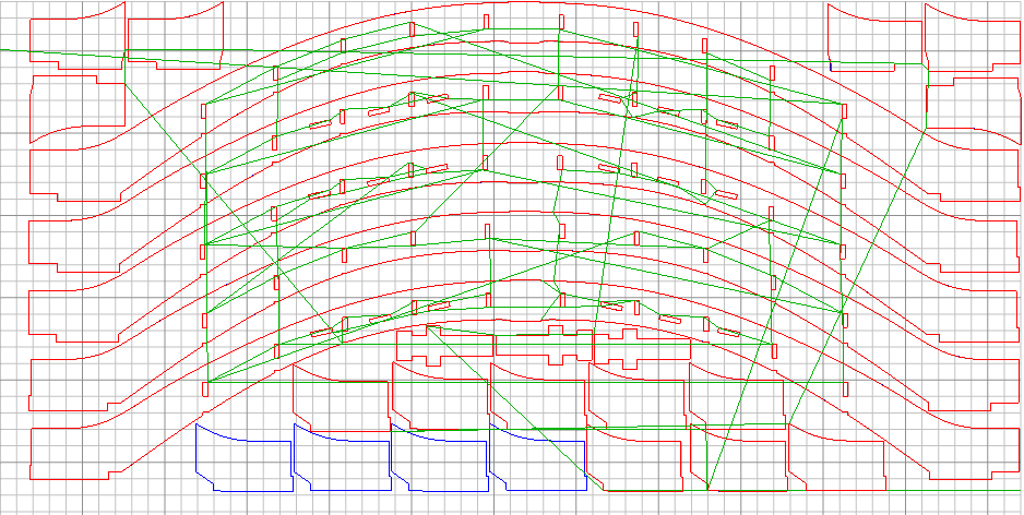
With greater certainty of the capabilities of the machine, I then proceeded to contact local wood suppliers to obtain the plywood necessary for the wooden bridges. As these sheets of plywood are often sold in sizes upwards of 4ft by 8ft, I first had to lay out my cut sheets (or at least estimate the rough sizes of the necessary cut sheets) before finding the most optimum way to cut up the plywood sheets to minimize wastage. This was done whilst considering the 1070mm by 480mm bed size of my laser cutter as well as the fact that laser attenuation would reduce the cutting capacity of the laser as it moved further from the source, and as such multiple passes / slower feed rates would have to be implemented to ensure that all parts were successfully cut out.
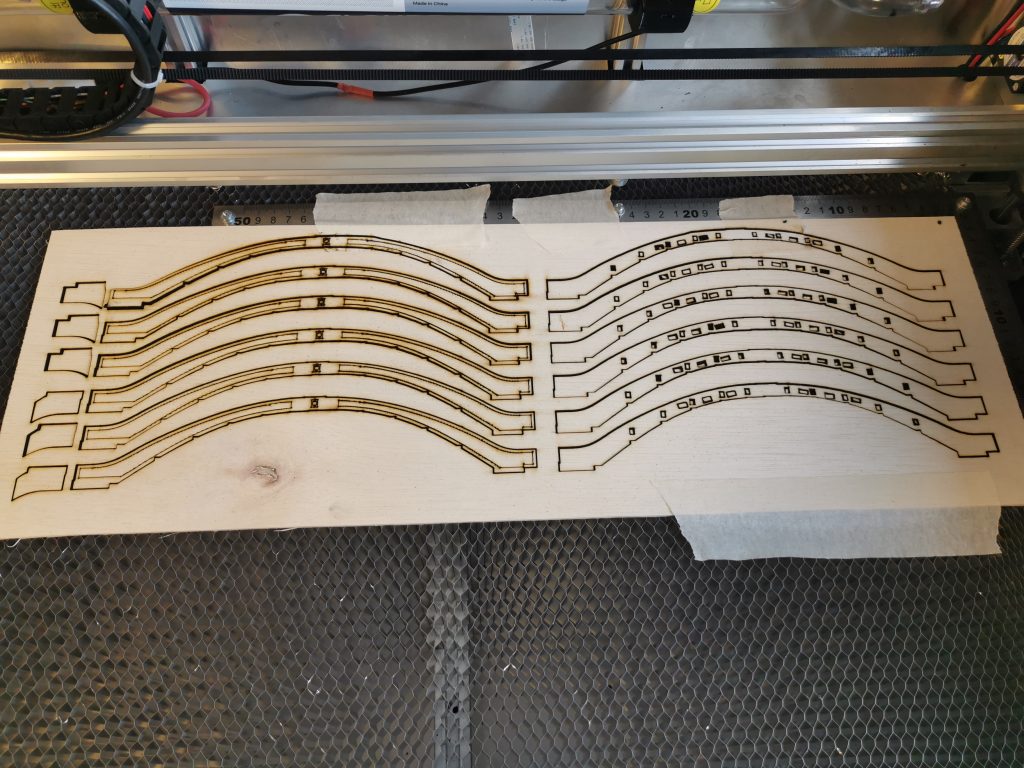
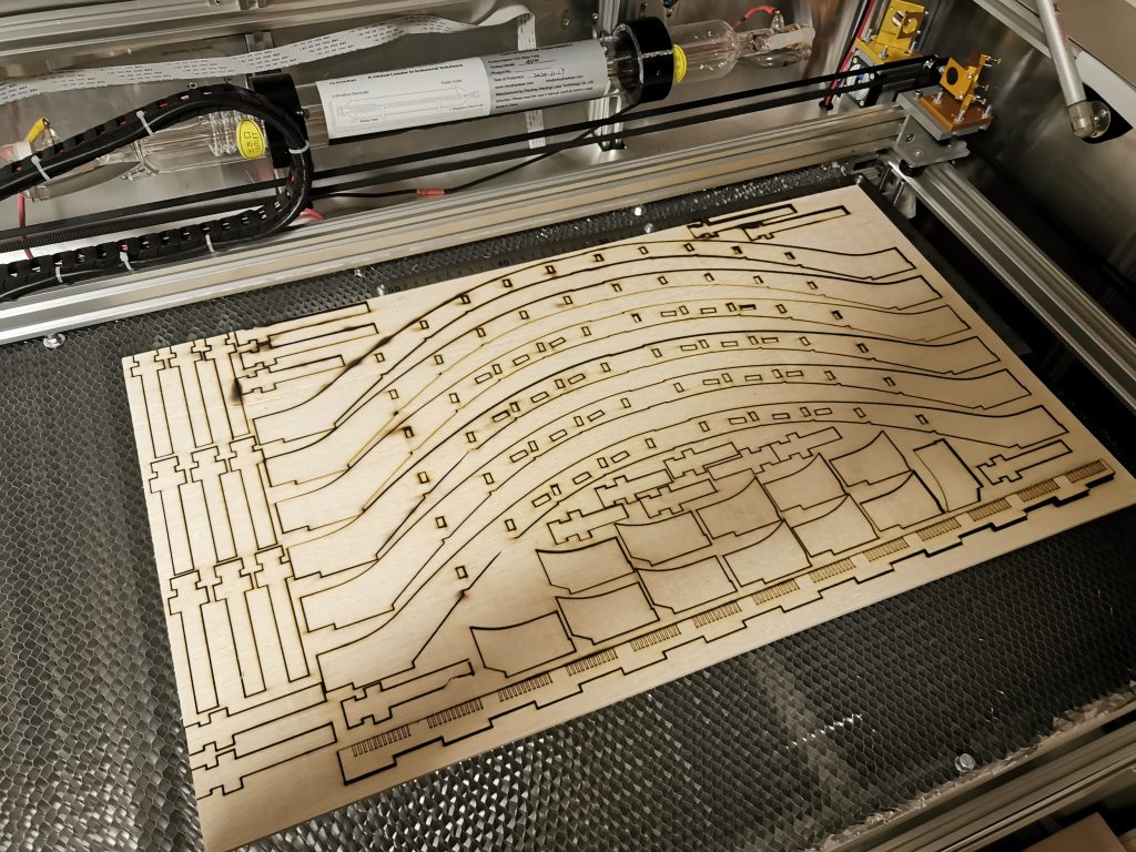
Eventually, I settled with cut sheets of 600mm by 400mm for the 5mm plywood. As for the acrylic, my friend had with him a dozen sheets of 600mm by 300mm white acrylic (3mm), and as such, I had to redesign cut sheets for the acrylic pieces.
With that I proceeded to cut the parts out of the laser cutter. I used LaserWeb as the GCODE “Slicer” (yes I shall be very loose with the terminology here) and the GCODE was also fed to the control board (Marlin RAMPS1.4) via a Raspberry Pi with the LaserWeb controller firmware installed as well.
I’ve grown to like LaserWeb’s simple and easy-to-use interface. More on that in another post where I share some tips and tricks on how to get LaserWeb to work for you.
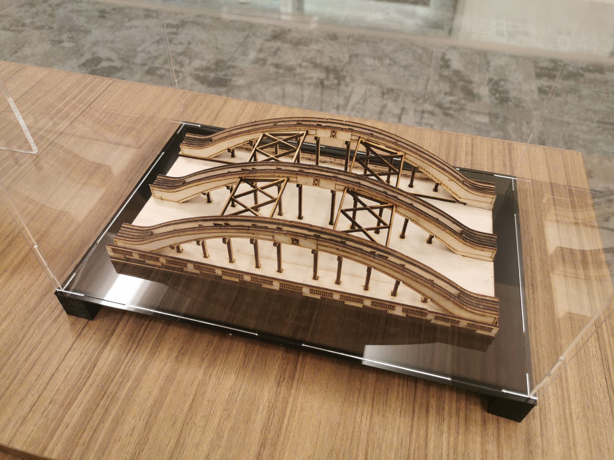
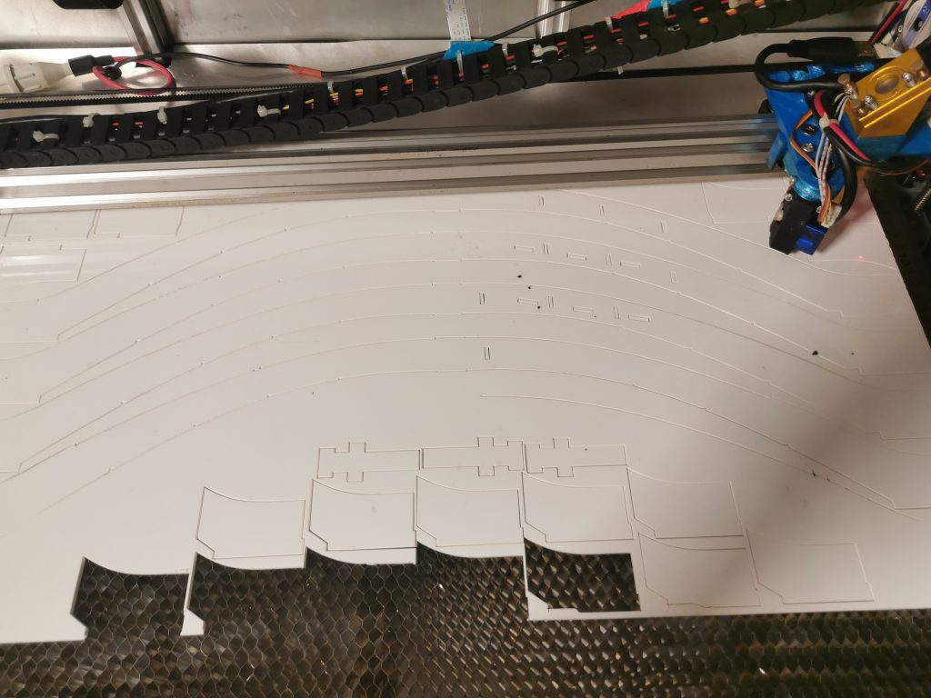
Despite the relative ease of creating and generating GCODE files, the acrylic bridge would still prove a real pain in all aspects to manufacture and assemble. For starters, the feed rate settings for acrylic were a lot lower than for plywood (possibly because acrylic doesn’t “burn” or “melt” that easily), and as such the average job time for acrylic was a lot longer. Couple that with the fact that the acrylic sheets at my disposal were 3mm versus the 5mm for plywood and that meant that since the design and dimensions were about identical, the acrylic bridge needed 1.5x more parts. Also the acrylic sheets were smaller in dimensions and hence overall I needed 3 sheets of plywood for a full bridge but 5 sheets for acrylic.
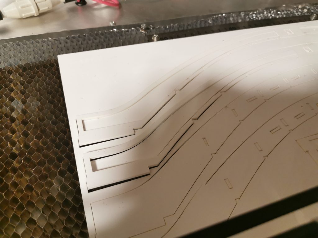
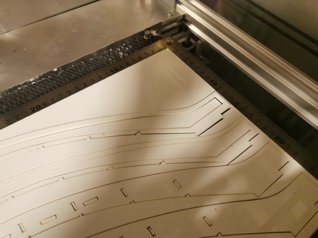
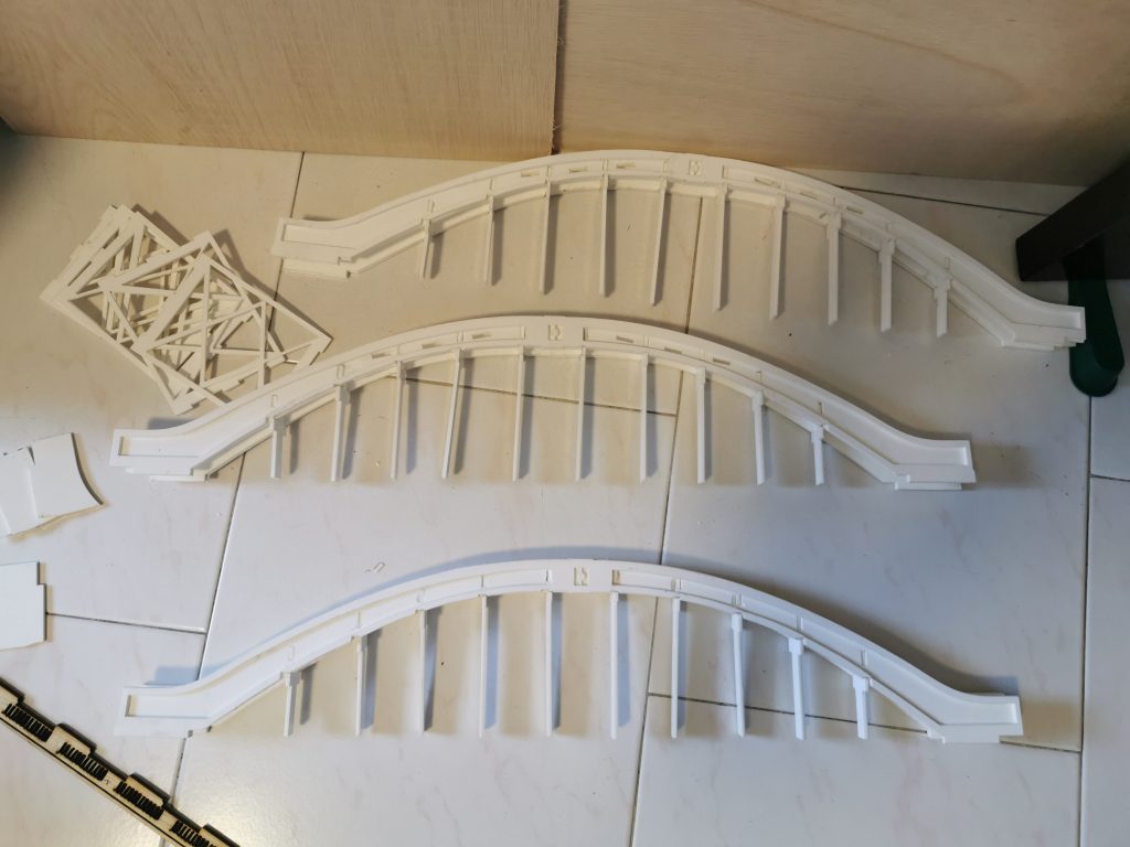
Moreover, acrylic had a tendency to warp when being cut, likely due to the nature of the melting process. This was extremely evident on larger parts like the arch pieces, where the sheet would visibly lift off the bed surface. This almost certainly led to small imperfections in the dimensions, especially the slots. I tried sticking the sheets down with masking tape before the job but that presented its own set of problems – namely in the form of a sticky, smelly residue probably formed when the laser burned through the tape. Perhaps painter’s tape would have worked better but since I had already produced sufficient parts by that point, I figured it would be best left determined in another project.
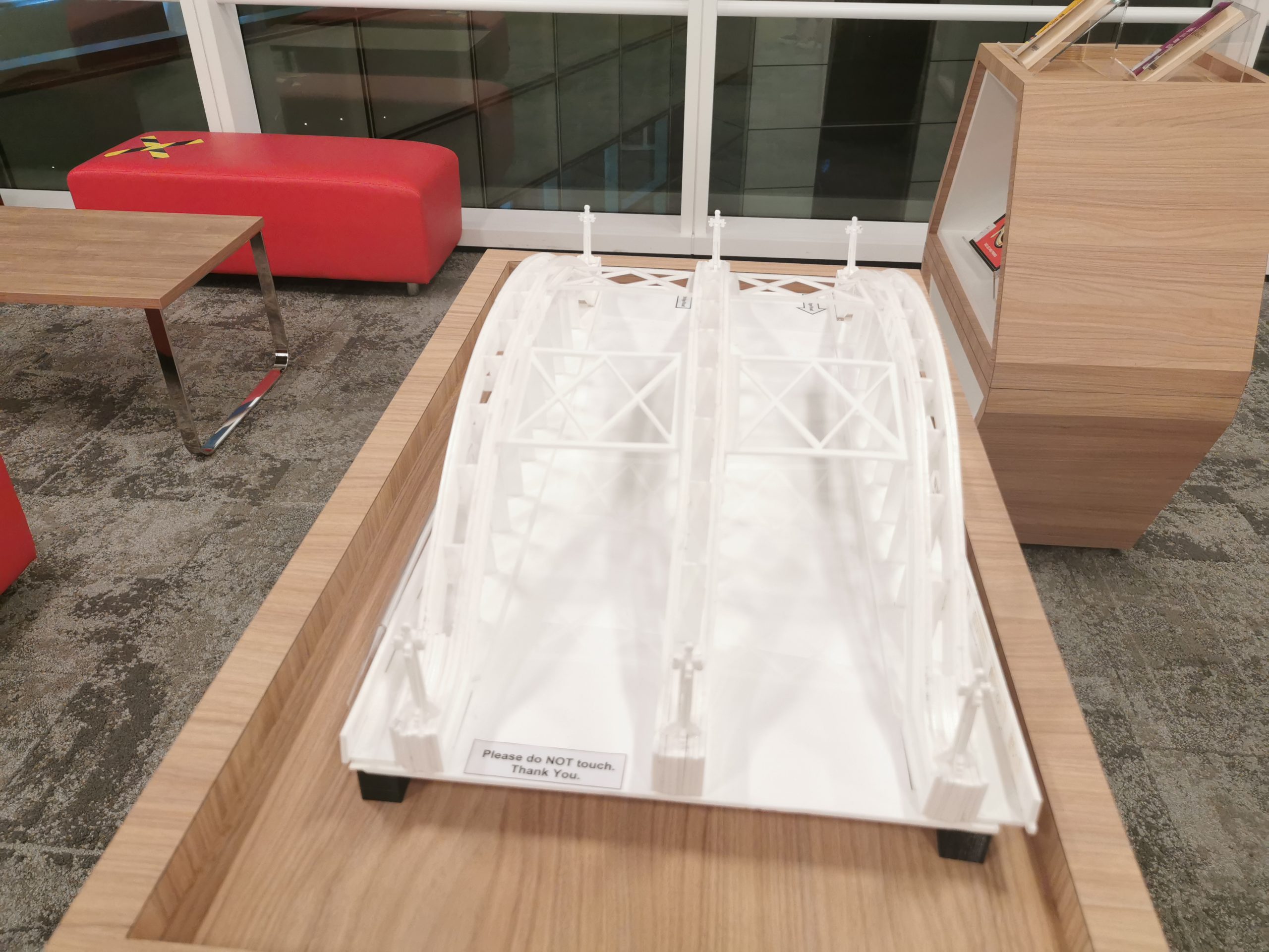
Then came the assembly which was also extremely frustrating. Unlike plywood, acrylic handles any stress to itself by cracking. Although this is good in the context of making clean, smooth cuts on the acrylic using something say like an acrylic knife, it is horrible when you are trying to friction fit pieces together. Couple that with the already strange and inconsistent behavior of acrylic when laser-cut and you have a recipe for a lot of broken parts.
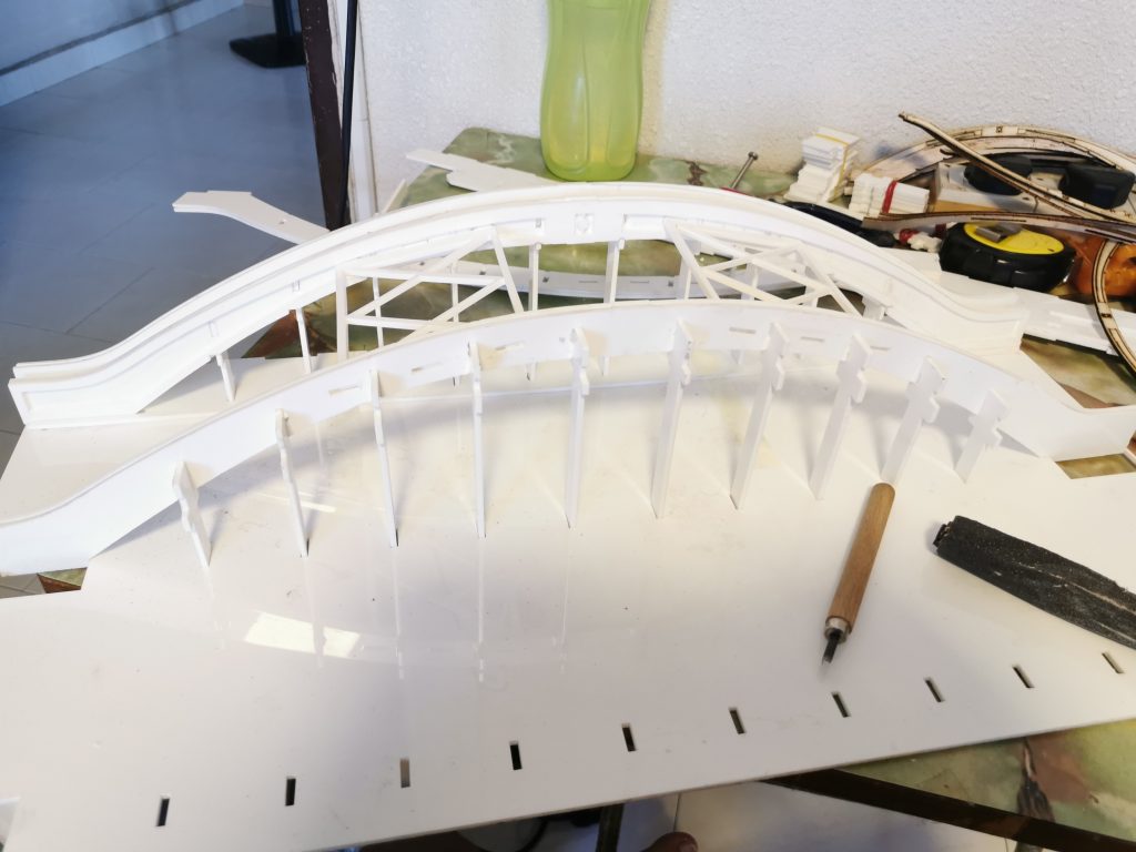
Finally, through countless re-cuts and a good deal of coaxing, I was finally able to assemble the acrylic bridge.
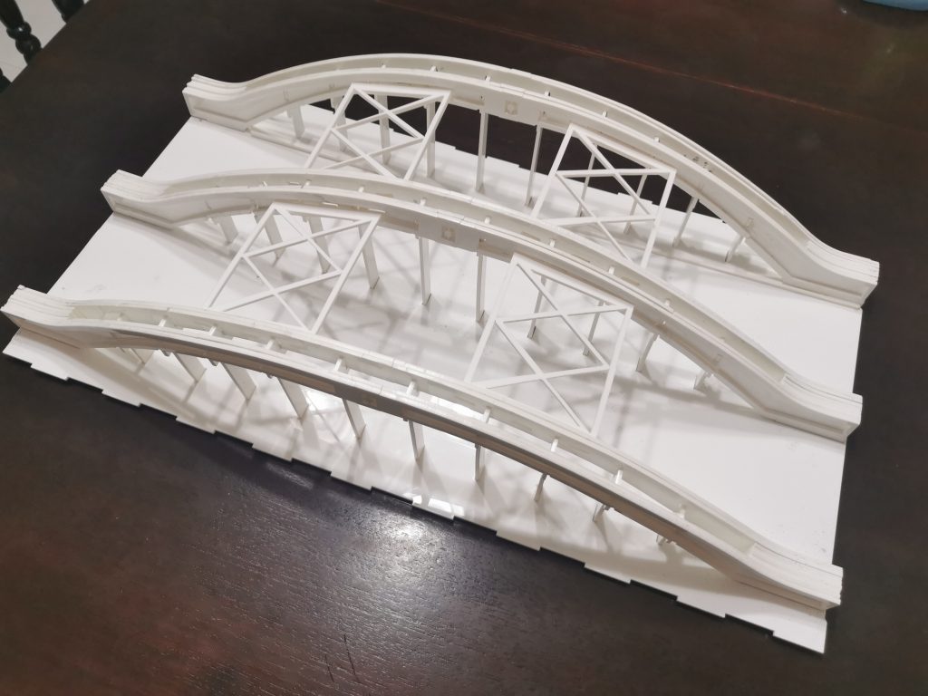
Overall, I am very satisfied with this project as, once again, this was the first time the laser cutter had been successfully employed to produce something (other than random cases for my electronics projects – which is also great but clearly not as complex or involved as this one). Although the machine served me well in this project, some problems associated with the sheer size of its build area begin to rear their ugly heads, most paramount being the slow but certain failure of the Z-steppers (because it was my bright idea to move the entire Z-axis (with the honeycomb aluminum sheet) vertically to achieve Z homing.
Well I guess it just goes to show that DIY often ain’t pretty, but it still works.